

Ferrite switch driver with self-feedback latch switch-off function
A switch driver and ferrite technology, applied in electronic switches, electrical components, pulse technology, etc., can solve problems such as reduced reliability, program runaway, and device failure, and achieve reduced switching losses, simple circuits, and reduced power consumption. heat effect
- Summary
- Abstract
- Description
- Claims
- Application Information
AI Technical Summary
Problems solved by technology
Method used
Image

Examples
Embodiment 1
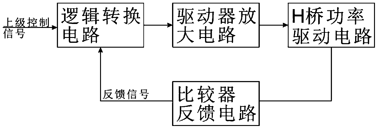
[0041] Example 1: see figure 1 , a self-feedback latch-off ferrite switch driver, comprising a logic conversion circuit, a driver amplifier circuit, an H-bridge power drive circuit, and a comparator feedback circuit;
[0042] The logic conversion circuit is used to receive the upper-level control signal and the feedback signal output by the comparator feedback circuit, and output two paths A1 and A2, wherein the upper-level control signal, the feedback signal, A1 and A2 are all level signals, and satisfy The following conditions:
[0043] In the initial state, the superior control signal is 0, the feedback signal is 0, A1=0, A2=0;
[0044] When the superior control signal changes from 0 to 1, A1=0, A2=1, at this time, if the rising edge of the feedback signal comes, A1=0, A2=0;
[0045] When the superior control signal changes from 1 to 0, A1=1, A2=0, at this time, if the rising edge of the feedback signal comes, A1=0, A2=0;
[0046] The driver amplifier circuit is used to re...
Embodiment 2
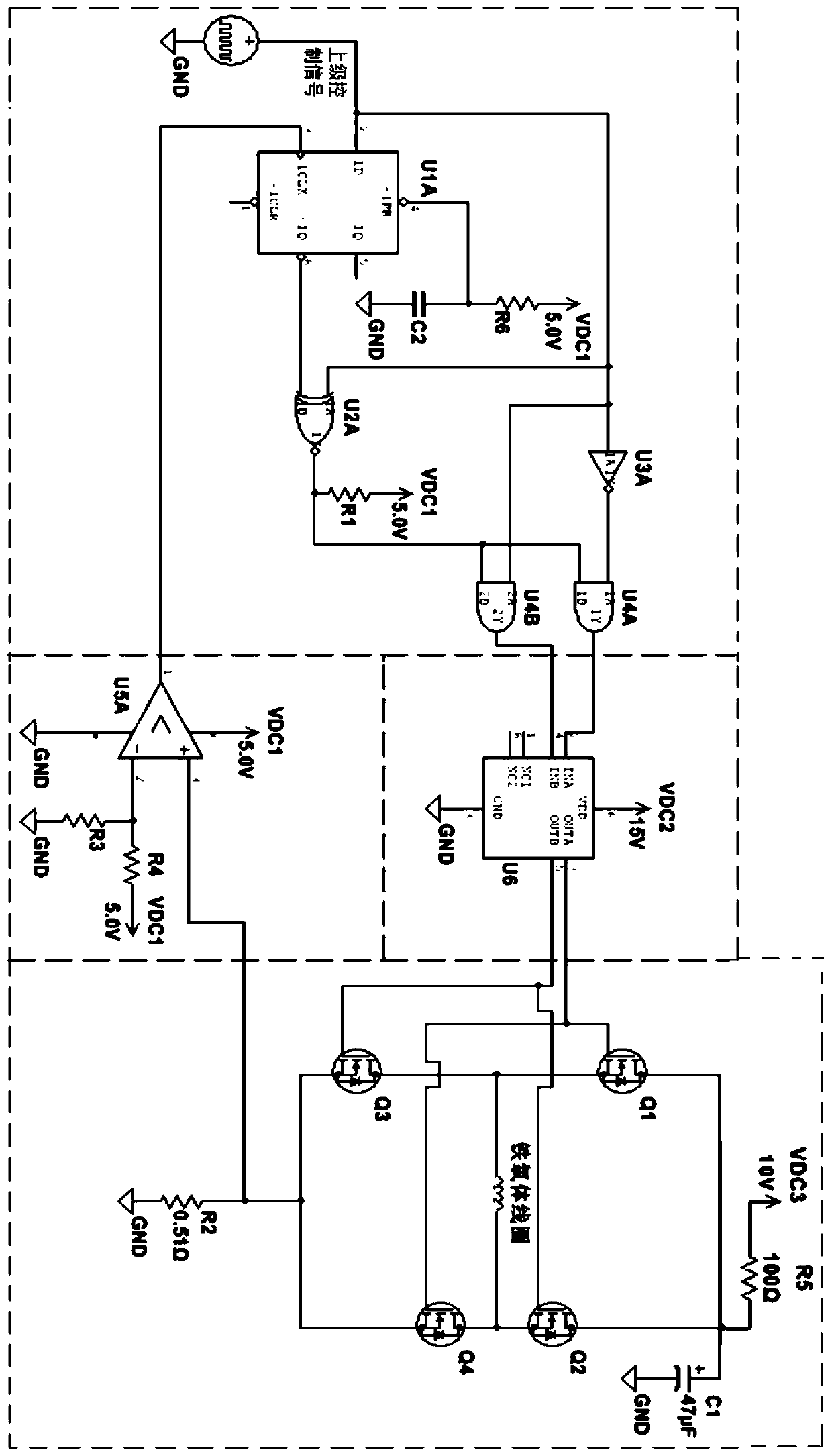
[0049] Example 2: see Figure 2-Figure 4 , on the basis of Embodiment 1, the present embodiment 2 provides the specific circuit forms of the logic conversion circuit, the driver amplifier circuit, the H-bridge power drive circuit, and the comparator feedback circuit respectively, as follows:
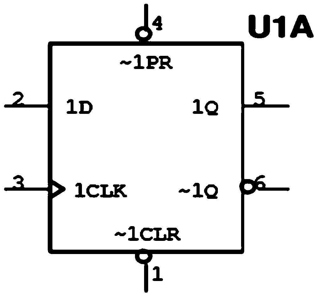
[0050] The logic conversion circuit includes a D flip-flop U1A, an exclusive NOR gate U2A, a NOT gate U3A, an AND gate U4A, and an AND gate U4B; pin 2 of the D flip-flop U1A is connected to a superior control signal, pin 3 is connected to a feedback signal, and pin 4 is connected to a feedback signal. The feet are divided into two circuits, one is connected to the 5V power supply through the resistor R6, and the other is grounded through the capacitor C2; the 2 feet of the D flip-flop U1A are also connected to the 1A terminal of the XOR gate U2A and the AND gate U4B, and are connected to the AND gate through the NOT gate U3A The 1A terminal of U4A; the 2A terminal of the XOR gate U2A is ...
PUM
 Abstract
Description
Claims
Application Information