Anti-chemical decontamination device

A decontamination and decontamination agent technology, applied to chemical instruments and methods, cleaning methods using liquids, cleaning methods and appliances, etc., can solve the problems of limited continuous working time, harsh working environment, low working efficiency, etc., to achieve Improve the efficiency of chemical defense and decontamination, reduce the amount of input, and reduce the effect of decontamination

Pending Publication Date: 2020-07-03
SHANGHAI GRAMAN INT FIRE EQUIP
View PDF0 Cites 0 Cited by
  • Summary
  • Abstract
  • Description
  • Claims
  • Application Information

AI Technical Summary

Problems solved by technology

[0003] However, modern tanks, armored vehicles and other weapons and equipment are equipped with a large number of advanced sensors, including optical and radar equipment, which are sensitive to temperature. When decontaminating, they are far away from the jet outlet to prevent equipment damage and failure, so that uneven surfaces or bending changes cannot be detected. Obtain decontamination, turbojet engine fuel consumption is extremely high (about 2000L of fuel per hour), continuous working time is limited, high temperature, high noise operating environment is harsh, and personnel operating conditions are poor. The decontamination form of this equipment is single, and only physical Elimination of operations, unable to release decontaminants for chemical disinfection, especially biological enzyme decontaminants in the future development direction
[0004] In addition, for areas with high air humidity and ground pollution, especially in areas with high humidity (relatively) and dew pollution in the south of the Yangtze River in my country, direct release of disinfectant dry powder is often used to achieve the purpose of rapid disinfection. The methods of spraying, dusting, and regional series blasting powder are used to operate, which has low operating efficiency and poor uniformity of spraying distribution, which seriously affects the disinfection effect

Method used


Image

  • Anti-chemical decontamination device
  • Anti-chemical decontamination device

Examples


Embodiment

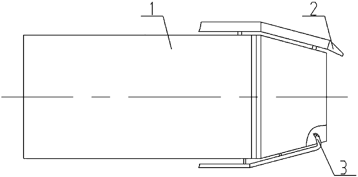
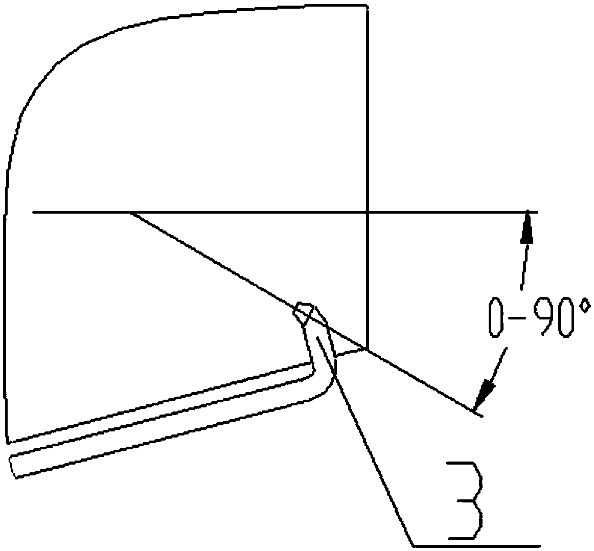
[0018] Please combine figure 1 and figure 2 Shown: a chemical-proof decontamination device provided in this embodiment, including a gas jet device 1, a liquid-based decontamination agent nozzle 2 and a solid-based powder decontamination agent nozzle 3, and the liquid-based decontamination agent nozzle 2 is installed on the gas jet Behind the spout of device 1, solid-base powder decontamination agent nozzle 3 is installed on the inside of the spout of gas jet device 1, and the injection direction of solid-base powder decontamination agent nozzle 3 is opposite to the jet flow axis direction of gas jet device, and is in line with the air flow. The included angle of the axis is 0-90 degrees.

[0019] The gas jet device 1 can spray the air after pressurizing it, and can use a motor, a hydraulic motor or an internal combustion engine as a fan driven by an internal combustion engine. The fan can be integrated or split, and can be an axial flow fan or a centrifugal fan. Or Roots bl...


PUM


Abstract

The invention discloses an anti-chemical decontamination device. The anti-chemical decontamination device comprises a gas jet device, a liquid-based decontaminating agent nozzle and a solid-based powder decontaminating agent nozzle. The liquid-based decontaminating agent nozzle is mounted on the rear of a nozzle of the gas jet device, the solid-based powder decontaminating agent nozzle is mountedon the inner side of the nozzle of the gas jet device, the jet direction of the solid-based powder decontaminating agent nozzle is opposite to the axis direction of jet stream of the gas jet device, and an included angle of the jet direction of the solid-based powder decontaminating agent nozzle and the jet stream axis is 0-90 degrees. According to the anti-chemical decontamination device, the gasjet is used as jet power, especially for the releasing mode of a solid-based powder decontaminating agent, the anti-chemical decontamination can be obviously improved, labor can be obviously saved, the consumption of the decontaminating agents can be obviously reduced, the input number of equipment and personnel can further be obviously reduced, and large-scale and large-area rapid decontamination operation after pollution can be carried out on facilities, the equipment and the ground.

Description

technical field [0001] The invention relates to a chemical prevention and decontamination device, which belongs to the technical field of chemical prevention and decontamination equipment. Background technique [0002] It is used for the decontamination of weapons and equipment after nuclear, biological and chemical pollution. The American and European armies mainly use water spray and high-pressure water jet scouring, including water spray and high-pressure water jet scouring containing chemical decontaminants. , The contact area between the jet and the pollutants is limited, the decontamination speed is slow and the efficiency is low, and it is not suitable for large-scale decontamination of equipment. In the 1960s, the former Soviet Union developed the TMC-65 turbine decontamination equipment, which installed the decommissioned turbojet engine on the truck chassis, and used the gas jet generated by the turbojet engine to stain the surface of large weapons such as tanks an...

Claims


Application Information

Patent Timeline
Patent Type & Authority Applications(China)
IPC IPC(8): B08B5/02B08B3/02B08B7/00
CPCB08B3/02B08B5/02B08B7/0021
Inventor 张铂赵伟梁申申王红兵程明刘震王超
Owner SHANGHAI GRAMAN INT FIRE EQUIP
Why Eureka
Try Eureka