An air cooling system for an electric centrifugal air compressor

An air cooling system and air compressor technology, applied in the direction of machines/engines, liquid fuel engines, mechanical equipment, etc., can solve the problems of increasing the length of the motor shaft, reducing the critical speed of the rotor system, and increasing the difficulty of installation, so as to improve the system Stability, improved surge margin, and small increase in cost

Active Publication Date: 2021-08-03
HYDROWELL (TAICANG) ENERGY TECH CO LTD
View PDF9 Cites 0 Cited by
  • Summary
  • Abstract
  • Description
  • Claims
  • Application Information

AI Technical Summary

Problems solved by technology

Its main disadvantage: the temperature and pressure of the external cooling air cannot be adjusted once the geometric dimensions of the flow channel are fixed, which easily makes it difficult to simultaneously meet the cooling air volume demand at high speed and the cooling air volume demand at low speed
[0005] Another cooling method is to set a cooling fan inside the motor. Through the rotation of the cooling fan, the cold air around the motor is absorbed into the inside of the motor for forced cooling. The length of the rotor system reduces the critical speed of the rotor system, resulting in a significant reduction in the maximum allowable operating speed of the motor of the same design, resulting in a decrease in the pressure ratio and flow of the air compressor
In addition, after the structure is complex, it is necessary to install a separate air intake filter to ensure the cleanliness of the inhaled air, which makes the installation more difficult, and the additional impeller and internal flow channel also significantly increase the volume and cost of the whole machine

Method used


Image

  • An air cooling system for an electric centrifugal air compressor

Examples


Embodiment Construction

[0022] The following describes several preferred embodiments of the present invention with reference to the accompanying drawings, so as to make the technical content clearer and easier to understand. The present invention can be embodied in many different forms of embodiments, and the protection scope of the present invention is not limited to the embodiments mentioned herein.

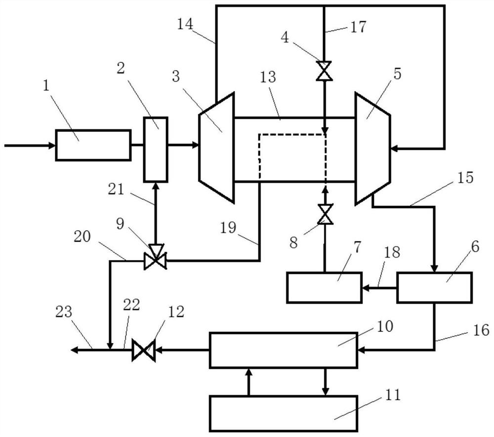
[0023] Such as figure 1 As shown, an air cooling system for an electric centrifugal air compressor includes a mixer 2, a first-stage compressor 3, a valve A4, a second-stage compressor 5, an intercooler 6, a second air filter 7, a valve B8, three Through valve 9, motor 13, compressed air pipe one 14, compressed air pipe two 15, compressed air pipe three 16, cooling air pipe one 17, cooling air pipe two 18, cooling exhaust pipe 19, exhaust pipe one 20, return air pipe 21 And exhaust manifold 23. Fresh air is filtered by the first air filter 1 and enters the mixer 2, and then enters the primary compre...


PUM


Abstract

The invention discloses an air cooling system for an electric centrifugal air compressor, which includes a flow mixer, a first-stage compressor, a valve A, a second-stage compressor, an intercooler, a second air filter, a valve B, a three-way valve, and a motor , Compressed air pipe 1, compressed air pipe 2, compressed air pipe 3, cooling air pipe 1, cooling air pipe 2, cooling exhaust pipe, exhaust pipe 1, return air pipe and exhaust main pipe; compressed air from the primary compressor Enter compressed air pipe 1, part of the compressed air enters cooling air pipe 1 at the branch point, and the compressed air in cooling air pipe 1 enters the motor through valve A for cooling; the compressed air from the secondary compressor enters compressed air pipe 2 and enters the middle The cooler comes out of an outlet of the intercooler and enters the cooling air pipe 2, is filtered by the second air filter, and enters the motor to cool the motor. The invention is applied to the electric centrifugal air compressor, and can realize better cooling effect and better comprehensive efficiency.

Description

technical field [0001] The invention relates to the field of electric air compressors, in particular to an air cooling system for electric centrifugal air compressors. Background technique [0002] Hydrogen fuel cell is an efficient and clean power device. The core system of a hydrogen fuel cell is its battery stack. In addition, there are four main auxiliary systems to ensure the normal and efficient operation of the battery stack, including: hydrogen supply system, gas supply system, water management system and thermal management system. Generally, a centrifugal air compressor driven by a permanent magnet synchronous motor is used to provide compressed air. At present, the mainstream method of heat dissipation inside the motor of the electric centrifugal air compressor is to use cold air as the medium to flow into the motor casing to take away the heat generated by the high-speed operation of the motor and bearings. [0003] The existing internal cooling air methods can ...

Claims


Application Information

Patent Timeline
Patent Type & Authority Patents(China)
IPC IPC(8): F04D29/58F04D29/66F04D25/08F04D25/06
CPCF04D25/06F04D25/08F04D29/5806F04D29/5846F04D29/667
Inventor 顾茸蕾王燕青
Owner HYDROWELL (TAICANG) ENERGY TECH CO LTD
Why Eureka
Try Eureka