Composite light spot laser system based on optical fiber output laser modules and machining head

A laser module and laser system technology, applied in laser welding equipment, metal processing equipment, manufacturing tools, etc., can solve the problems of difficult laser optical system design, expensive high-power beam combiner, and low device reliability

Pending Publication Date: 2020-07-07
方强
View PDF0 Cites 1 Cited by
  • Summary
  • Abstract
  • Description
  • Claims
  • Application Information

AI Technical Summary

Problems solved by technology

[0006] The first is the technical problems in the system: 1. During the laser beam combining process, the beam combiner must deal with the inevitable light leakage during the beam combining process. Thermal management is very difficult, resulting in low reliability of the device; 2. The beam combiner It is not perfect, so that the beam quality seriously deviates from its theoretically achievable level, which brings difficulties to the design of the subsequent laser optical system; 3. The laser optical system will absorb heat and cause the temperature to rise under the action of high-power laser, because glass is a bad heat conductor , the lens can only be cooled by the lens frame at the edge, which leads to a high temperature in the center of the lens, forming the so-called thermal lens effect, the greater the power, the more obvious the thermal lens effect, which will cause the drift of the light spot and affect the processing quality
[0007] The second is the cost issue: 1. High-power beam combiners are very ex

Method used


Image

  • Composite light spot laser system based on optical fiber output laser modules and machining head
  • Composite light spot laser system based on optical fiber output laser modules and machining head
  • Composite light spot laser system based on optical fiber output laser modules and machining head

Examples


Embodiment 1

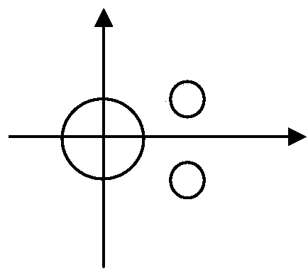
[0060] Embodiment 1: According to the technical scheme of the laser system based on multiple optical fiber output laser modules proposed by the present invention, in a certain embodiment of the present invention, it is necessary to realize the light synthesis of 49 optical fiber output laser modules into a light spot structure, and the light spot is required 1.8 mm in diameter. The system uses Figure 4A The structure of 7 collimating lenses and 1 focusing lens is shown, the optical axes of the 7 collimating lenses are parallel, the focal lengths of the 7 collimating lenses are the same, and the front focal planes coincide, the optical axes of the focusing lens FL and the collimating lens The optical axis is parallel to and coincides with the optical axis of the collimating lens in the center; the output power of the semiconductor laser module with a wavelength of 915 nanometers is 120 watts, the output fiber core diameter is 105 microns, the cladding diameter is 125 microns, ...

Embodiment 2

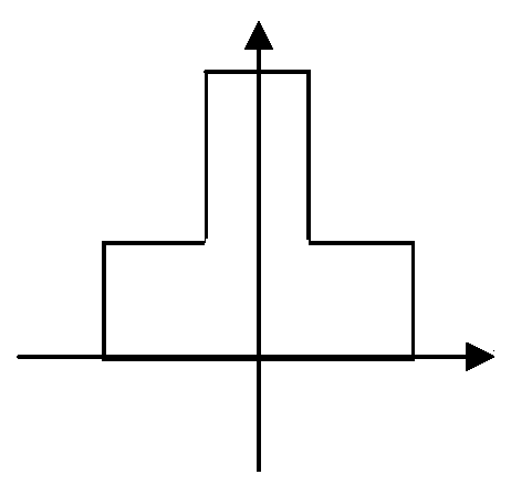
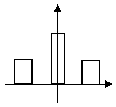
[0061] Embodiment 2: According to the technical scheme of the laser system based on multiple optical fiber output laser modules proposed by the present invention, in a certain embodiment of the present invention, a spot with high power in the central area and low power in the edge area is required, and the Figure 4A In the shown structure of 7 collimating lenses and 1 focusing lens, the optical axes of the 7 collimating lenses are parallel, the optical axis of the focusing lens FL is parallel to the optical axis of the collimating lens, and the light beam of the collimating lens located in the center Axis coincidence; In this embodiment, 7 fiber output laser modules are fiber lasers with a wavelength of 1064 nanometers, power 500 to 1000 watts, the core diameter of each module output fiber is 20 microns, the numerical aperture is 0.06, and the fiber cladding diameter 400 microns. Among the 7 collimating lenses, 6 have a focal length of 50 mm, 1 has a focal length of 25 mm, th...

Embodiment 3

[0063] Embodiment 3: According to the technical scheme of the laser system based on multiple optical fiber output laser modules proposed by the present invention, in a certain embodiment of the present invention, a light spot with a sheet-like converging structure is required, and the collimating lens and the converging lens in the optical path use Figure 7 In the structure shown, 6 lenses are arranged one-dimensionally in one plane, the optical axes of the 6 lenses are parallel, the focal lengths of the 6 lenses are the same, and the front focal planes coincide, the optical axis of the focusing lens FL is parallel to the optical axis of the collimating lens , the distribution center of the six collimating lenses coincides with the optical axis of the focusing lens. In this embodiment, the 6 fiber output laser modules are fiber lasers with a wavelength of 1064 nanometers and a power of 500 to 1000 watts. The core diameter of the output fiber of each module is 20 microns, the ...


PUM

PropertyMeasurementUnit
Diameteraaaaaaaaaa

Abstract

The invention discloses a composite light spot laser system based on a plurality of optical fiber output laser modules and a machining head. A plurality of low-power light sources are directly used togenerate a composite light spot through an optical system, and the laser system is used for manufacturing the machining head. The composite light spot laser system based on the optical fiber output laser modules comprises the optical fiber output laser modules, a plurality of collimating lenses corresponding to the optical fiber output laser modules and a focusing lens; the output optical fiber end surfaces of the optical fiber output laser modules are located near the front foci of the collimating lens corresponding to the optical fiber output laser modules, the collimating lens at least comprises one lens; the focusing lens at least comprises one lens and is located behind the collimating lens. The use of a high-power laser beam combiner is avoided, the laser output is dispersed at a plurality of points, heat concentration is avoided, and the reliability problems caused by the beam combiner are solved; the beam quality is improved; the thermal problem in the laser optical system canbe greatly eliminated by technical means; by dispersing the thermal problem and adopting heat conduction measures, the impact of the thermal effect can be greatly reduced, and the reliability and characteristics of the system can be improved.

Description

technical field [0001] The invention relates to a laser system and a processing head, in particular to a composite spot laser system based on multiple optical fiber output laser modules and a laser processing head using the system, which belongs to the technical field of laser processing and can be widely used in the laser processing industry . Background technique [0002] In laser processing applications, laser spots with various structures are required to ensure the effect of laser processing. For example: for welding or cutting compound spot with high center power and small edge power, see Figure 1-1A ;Multi-spot spot for welding, see Figure 1-1B And Figure 1-2; for cladding, welding, quenching strip spot, rectangular spot and circular spot, etc., see Figure 1-3. [0003] currently implemented Figure 1-1A The light spot shown usually adopts a dual-wavelength light source, and the light path is as follows: diagram 2-1 As shown, the lights of different wavelengths e...

Claims


Application Information

Patent Timeline
IPC IPC(8): B23K26/064B23K26/067B23K26/70
CPCB23K26/0673B23K26/064B23K26/702
Inventor 方强方笑尘
Owner 方强
Why Eureka
Try Eureka