Rock geometry-mechanics parameter acquisition method and holographic scanning system
A technology of mechanical parameters and acquisition methods, applied in scientific instruments, material analysis by optical means, and testing of material strength by applying stable tension/pressure, etc. complex, inferior, etc.
- Summary
- Abstract
- Description
- Claims
- Application Information
AI Technical Summary
Problems solved by technology
Method used
Image
Examples
Embodiment 1
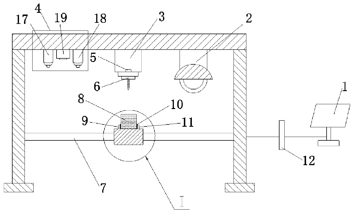
[0085] Such as figure 1 As shown, the rock geometry-mechanical parameters holographic scanning system includes an observation mechanism 4, a multi-scale penetrating mechanism 3, a grinding mechanism 2, a rock sample installation mechanism, and a control three-axis precision motion platform 7. Motion platform 7, observation mechanism 4, multi-scale penetrating mechanism 3, grinding mechanism 2, industrial computer 1 of rock sample installation mechanism; among them,
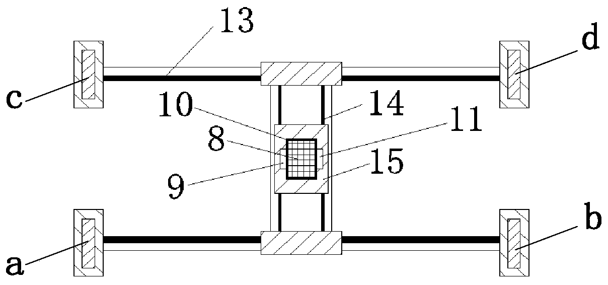
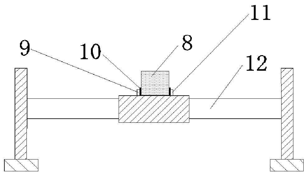
[0086] Such as figure 2As shown, the three-axis precision motion platform 7 is purchased from common commercially available equipment, which includes a first support column a, a second support column b, a third support column c and a fourth support column d; the first support column a and the second support column Between the two supporting columns b, and between the third supporting column c and the fourth supporting column d, a horizontal longitudinal beam is erected, and each of the two horizontal longitudina...
Embodiment 2
[0097] Such as Figure 6 As shown, a method for obtaining rock geometric-mechanical parameters realized by the rock geometric-mechanical parameter holographic scanning system of the above-mentioned embodiment 1, the specific steps are as follows:
[0098] S1. Place a rock sample 8 taken from the target test rock on the second platform 15. The bottom of the rock sample 8 is consolidated, and the rock sample is moved by the three-axis precision motion platform 7 to move it to the observation platform. Below the mechanism, specifically, the central axis of the rock sample 8 coincides with the micro-projector 19; then utilize any camera in the two cameras arranged obliquely above the rock sample to obtain an image of the upper surface of the rock sample;
[0099] S2. Divide the upper surface of the rock sample into 50×50 grids with relatively high resolution by laser, and use a triangular Belleville indenter with a side length of 0.5 mm to load each grid at a preset loading rate w...
Embodiment 3
[0125] A method for obtaining rock geometric-mechanical parameters realized by the rock geometric-mechanical parameter holographic scanning system of the above-mentioned embodiment 1, the steps of which are the same except that step S2 is different from that of embodiment 1.
[0126] Specifically, the specific steps of step S2 in this embodiment are:
[0127] The upper surface of the rock sample is divided into 40×40 grids with relatively low resolution by laser, and the twist drill bit is used to drill in each grid at the preset drilling speed w 2 =75mm / min and drilling depth L 2 = 5mm for drilling, and at the same time, in each cutting process, the dynamic signal P(t) of the feed force changing with time is obtained through the feed force sensor connected to the twist drill bit, and obtained through the torque sensor arranged on the adjacent side of the twist drill bit The dynamic signal M(t) of torque changing with time, the dynamic signal D of displacement changing with t...
PUM
 Abstract
Description
Claims
Application Information
 - R&D
- Intellectual Property
- Life Sciences
- Materials
- Tech Scout
- Unparalleled Data Quality
- Higher Quality Content
- 60% Fewer Hallucinations
Browse by: Latest US Patents, China's latest patents, Technical Efficacy Thesaurus, Application Domain, Technology Topic, Popular Technical Reports.
© 2025 PatSnap. All rights reserved.Legal|Privacy policy|Modern Slavery Act Transparency Statement|Sitemap|About US| Contact US: help@patsnap.com


