Three-wire series connection type electronic water gauge circuit

An electronic water gauge and sub-circuit technology, applied in the direction of the liquid level indicator for physical variable measurement, can solve the problems of reducing the anti-interference performance, reducing the water level collection speed, and difficult to adapt to the data update frequency.

Pending Publication Date: 2020-07-14
GUANGZHOU AOGE INTELLIGENT TECH CO LTD
View PDF3 Cites 0 Cited by
  • Summary
  • Abstract
  • Description
  • Claims
  • Application Information

AI Technical Summary

Problems solved by technology

[0007] Since the above solution uses a digital logic chip: it requires more complex sequential circuits and multiple interface pins of the microprocessor (MCU), too many cascaded stages of detection electrodes will reduce the water level acquisi...

Method used


Image

  • Three-wire series connection type electronic water gauge circuit
  • Three-wire series connection type electronic water gauge circuit
  • Three-wire series connection type electronic water gauge circuit

Examples


Embodiment approach 1

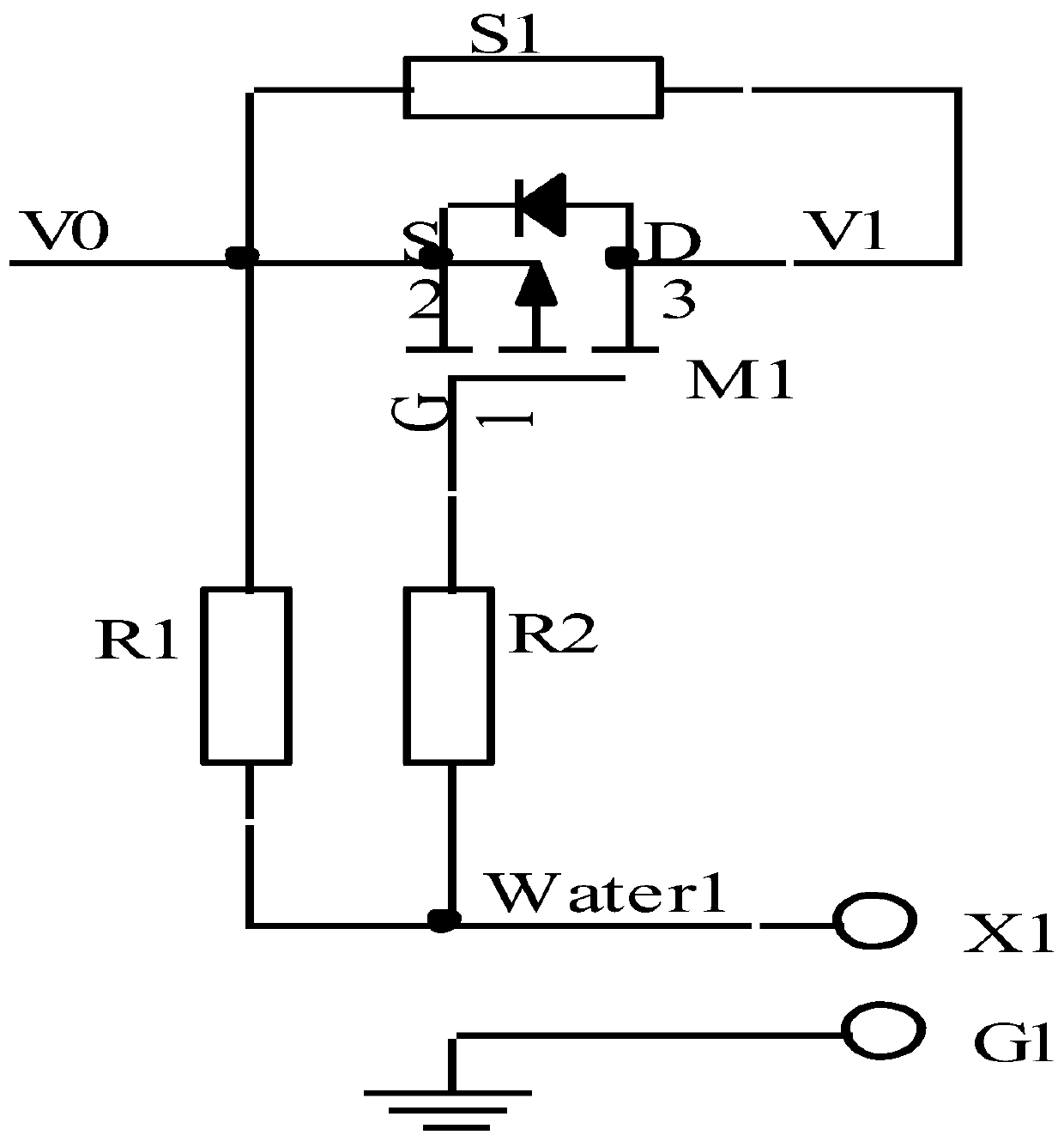
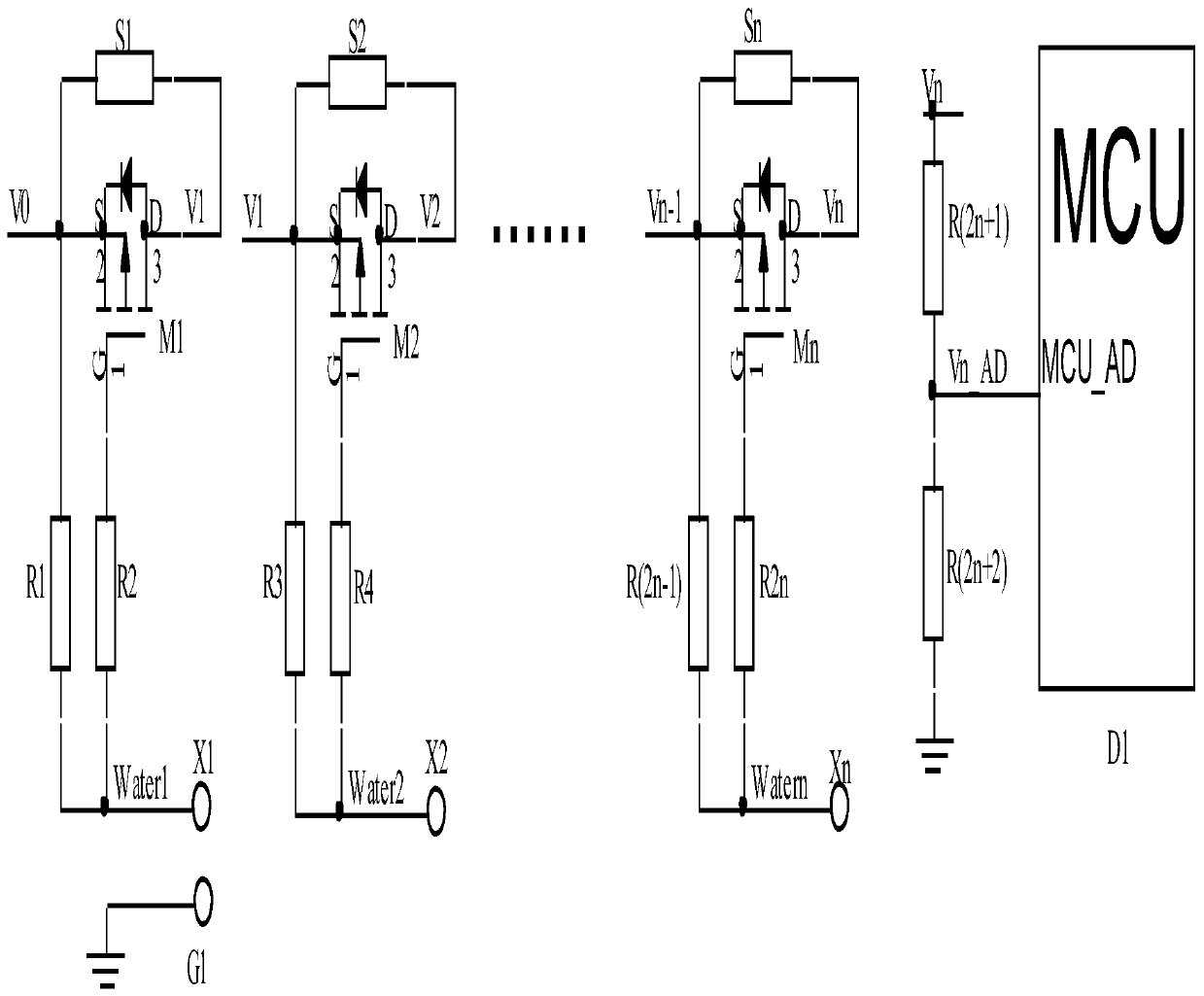
[0032] The invention discloses a three-wire series electronic water gauge circuit, which is composed of cascaded water level detection sub-circuits arranged in series at equal intervals, a voltage dividing circuit, a microprocessor and the like. The water level detection sub-circuit is composed of PMOS tube M1, resistors S1, R1, R2, detection electrode X1 and common pole G1. In the circuit, the signal Water1 is connected to resistors R1 and R2 at the same time, the other leg of R1 and the source of the PMOS tube are connected to the power supply V0 at the same time, the other leg of R2 is connected to the gate of the PMOS tube, the drain of the PMOS tube is the water level detection signal V1, and the current limiting resistor S1 is connected to the PMOS tube. tube source and drain.

[0033] PMOS tube type selection: Considering that the water level detection sub-circuit has a large number of cascaded stages, it is best to choose a PMOS tube with low conduction resistance Rds ...

Embodiment approach 2

[0046] The difference between the second embodiment and the first embodiment is as follows in the selection and calculation method of the current limiting resistor.

[0047] At present, the E48, E96, and E192 series resistors used in electronic products are equal-proportion resistors, and their public ratios q are 1.052, 1.025, and 1.012, respectively, and their accuracy errors are ±2%, ±1%, and ±0.5% / 0.2%. / 0.1%, E192 resistors have high precision and are more expensive. We give priority to using E96 resistors with high cost performance.

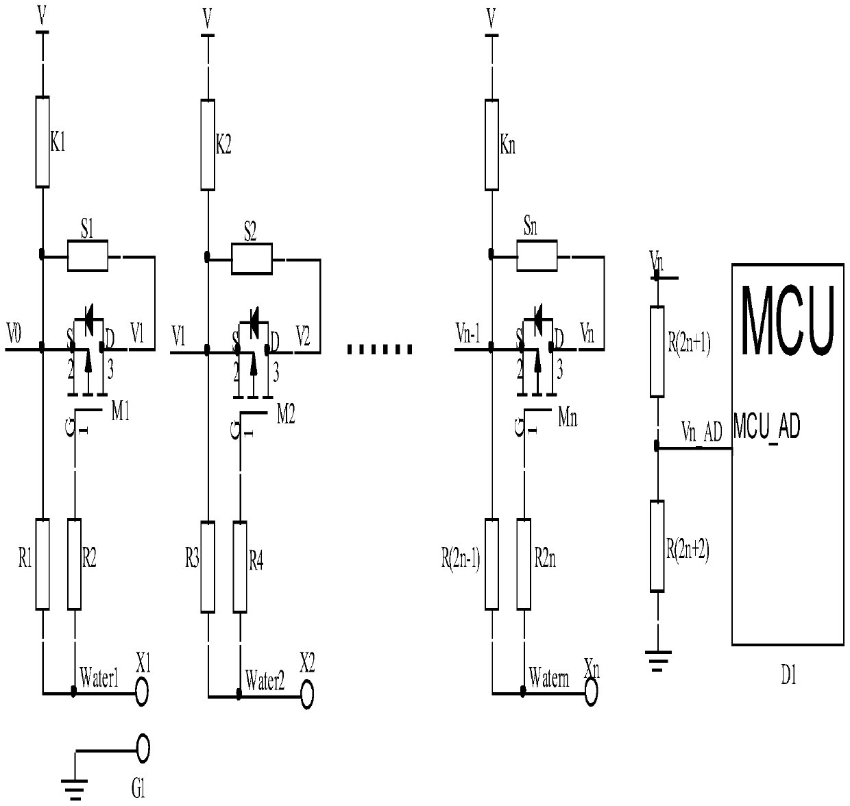
[0048] According to the geometric sequence formula, it can be seen that the common ratio q=1.025, and the nth level resistance Sn=S1*q n-1 , the total resistance Sum=S1+S2+S3+......+Sn=S1(1-q n ) / (1-q), considering the actual situation, V0=VCC, that is, R(2n+1)=0, m=0.

[0049] For the convenience of derivation and calculation, we renumbered the current-limiting resistors and sampling resistors to obtain Sn...S3, S2, S1, S0, K1 needs to b...


PUM


Abstract

The invention discloses a three-wire series connection type electronic water gauge circuit. The circuit is composed of multiple stages of water level detection sub-circuits which are arranged in series at equal intervals in a cascade mode, a voltage division circuit, a microprocessor and the like. Eachwater level detection sub-circuit is composed of a PMOS transistor, a resistor, a detection electrode and a common electrode. The fact of whethera water body makes contact with a detection electrode or not is used for deciding connection and disconnection of a PMOS tube, then whether a low-impedance path is provided for detection signal transmission or not is determined, multi-stage series transmission is conducted, finally, a microprocessor MCU conducts analog-digital conversion through AD to obtain a voltage value, the voltage value is compared with reference voltage, and water level information is obtained. The three-wire system replaces the conventional four-wire system, an analog signal replaces a digital signal, the circuit has the characteristics of ultra-low power consumption, wide power supply voltage range, wide working temperature range, light weight, small size, high response speed, high interference resistance, high corrosion resistance and the like, IP68 can be achieved through waterproof treatment of soft pouring glue, and the flexible electronic water gauge is further processed.

Description

technical field [0001] The invention relates to the technical field of water level measurement, in particular to a three-wire series electronic water gauge circuit. Background technique [0002] The electronic water gauge (electrode water level sensor) is a water level measurement sensor that uses the conductivity of water to collect water depth information through signal detection electrodes arranged in series at equal intervals. The signal detection electrodes of the acquisition circuit can judge whether the electrodes are high or low according to the potential. contact with bodies of water. The water depth is judged according to the number of electrodes submerged in the water. Most of the electronic water gauges on the market are composed of circuit boards, common poles, detection electrodes, epoxy resin, and metal casings. The common poles are connected to the metal casing, and the detection electrodes are connected to the PCB circuit board. Good contact with water. ...

Claims


Application Information

Patent Timeline
IPC IPC(8): G01F23/24
CPCG01F23/24
Inventor 陈石平彭进双谈书才张海彬何传志吴海权徐恒兴
Owner GUANGZHOU AOGE INTELLIGENT TECH CO LTD
Why Eureka
Try Eureka