Transmitting system based on visible light communication

A technology for visible light communication and transmission systems, applied in transmission systems, electromagnetic transmitters, short-range systems, etc., can solve the problems of large background noise interference, limited, uneven frequency response curve, etc.

Pending Publication Date: 2020-07-17
NANCHANG UNIV
View PDF0 Cites 3 Cited by
  • Summary
  • Abstract
  • Description
  • Claims
  • Application Information

AI Technical Summary

Problems solved by technology

Therefore, when the LED is used for visible light signal modulation, the frequency response of the signal will be affected by the frequency characteristics of the LED, and the high-frequency component of the signal will be suppressed, which will cause serious distortion of the signal, increase the bit error rate of the system, and affect the stability of the system. sex
[0004] In the visible light communication system, due to the uneven frequency response curve of the LED transmitting tube and photoelectric receiving tube, the optical channel has problems such as serious multipath effects and large background noise interference, the modulation bandwidth and data transmission rate of the VLC system have been seriously affected. restrict
Although the use of high-order modulation techniques such as OFDM and multi-carrier modulation techniques such as DMT can increase the channel capacity and data transmission rate of the VLC system to a certain extent, it is difficult to effectively improve the transmission performance due to the limited modulation bandwidth of the VLC system.

Method used


Image

  • Transmitting system based on visible light communication
  • Transmitting system based on visible light communication
  • Transmitting system based on visible light communication

Examples


Embodiment Construction

[0029] The present invention will be further described below in conjunction with the accompanying drawings and specific embodiments.

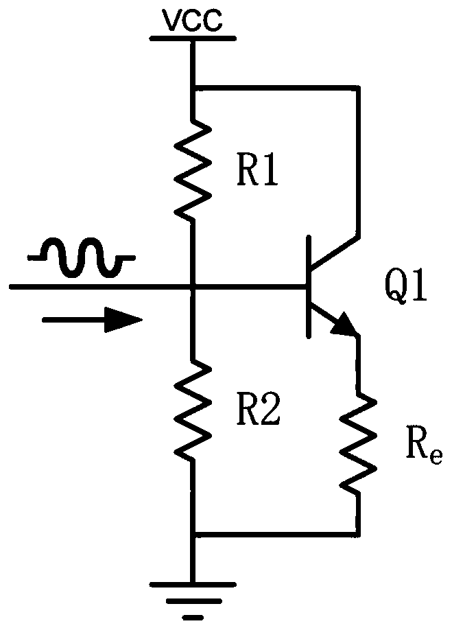
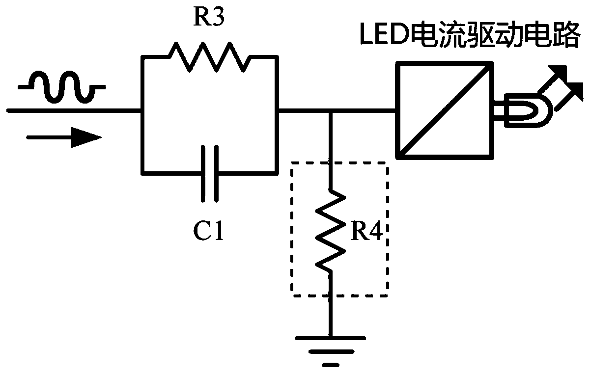
[0030] Such as figure 1 It is a visible light communication transmitting system according to the present invention, comprising: a common collector amplifier circuit, an analog pre-equalizer, an LED current drive circuit, and a light emitting diode. The common collector amplifying circuit is connected with the analog equalizer, the analog pre-equalizer is connected with the LED current drive circuit, and the LED current drive circuit is connected with the light emitting diode.

[0031] The common collector amplifying circuit can easily perform impedance matching on the input port of the whole circuit while obtaining extremely small output impedance to the subsequent stage.

[0032] Such as figure 2 It is the common collector amplifying circuit of the specific embodiment of the present invention, consists of the first resistor R1, the second r...


PUM


Abstract

A transmitting system based on visible light communication is characterized by comprising a common collector amplifying circuit, an analog pre-equalizer, an LED current driving circuit and a light emitting diode, wherein the common collector amplifying circuit is connected with the analog pre-equalizer, the analog pre-equalizer is connected with the LED current driving circuit, and the LED currentdriving circuit is connected with the light emitting diode. A third resistor and a first capacitor is connected between the input end and the output end of the pre-equalizer after connected in parallel, and a fourth resistor is connected between the output end of the pre-equalizer and the ground. The passive analog pre-equalizer is inserted between active circuits formed by the common collector amplifying circuit and the LED current driving circuit. The design of a common base structure is used behind the analog pre-equalizer, the input impedance is very small, the frequency response of the analog pre-equalizer is ensured not to tend to be flat at a high frequency band too early, the frequency response of the LED can be effectively compensated and corrected, and the modulation bandwidth and the data transmission rate of the system are improved.

Description

technical field [0001] The present invention relates to the field of visible light communication, in particular to a transmission system based on visible light communication. Background technique [0002] With the development of wireless communication, spectrum resources are increasingly scarce, and it is imminent to find wider and more efficient communication frequency bands and wireless access methods that are more conducive to popularization. Visible light communication technology was born under this background. It can simultaneously realize the two functions of high-speed information communication and daily lighting at a relatively low cost. Compared with traditional radio frequency communication technology, visible light communication technology has the characteristics of safety, green environmental protection, no electromagnetic interference, wide frequency range, etc., and is suitable for applications in many fields such as smart home, intelligent transportation, unde...

Claims


Application Information

Patent Timeline
Patent Type & Authority Applications(China)
IPC IPC(8): H04B10/116H04B10/50
CPCH04B10/116H04B10/502
Inventor 陈煊邦罗雨桑曹凡王玉皞闵汉红
Owner NANCHANG UNIV
Why Eureka
Try Eureka