Lamination method of solar cell module and the solar cell module

A technology for solar cells and modules, applied in the direction of lamination, electrical components, lamination devices, etc., can solve the problems of low yield, uneven film distribution, overflow, etc., to improve yield, uniform stress, and avoid deformation Effect

Pending Publication Date: 2020-07-21
东君新能源有限公司
View PDF0 Cites 2 Cited by
  • Summary
  • Abstract
  • Description
  • Claims
  • Application Information

AI Technical Summary

Problems solved by technology

[0005] Therefore, the technical problem to be solved by the present invention is to overcome the defects in the prior art that the direct formation of a curved surface structure by one-time lamination will lead to uneven distribution or even overflow of the adhesive film and low yield, thereby providing a laminated layer of a solar cell module Pressure method and solar cell module

Method used


Image

  • Lamination method of solar cell module and the solar cell module
  • Lamination method of solar cell module and the solar cell module
  • Lamination method of solar cell module and the solar cell module

Examples


Embodiment 1-9

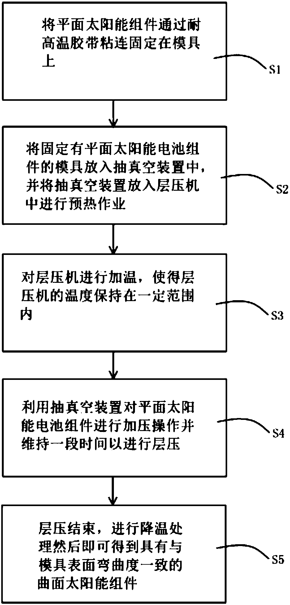
[0030] Such as figure 1 As shown, the present embodiment relates to a lamination method of a solar cell module, comprising the following steps:

[0031] S1. Fix the planar solar cell module on the mold by adhesive tape.

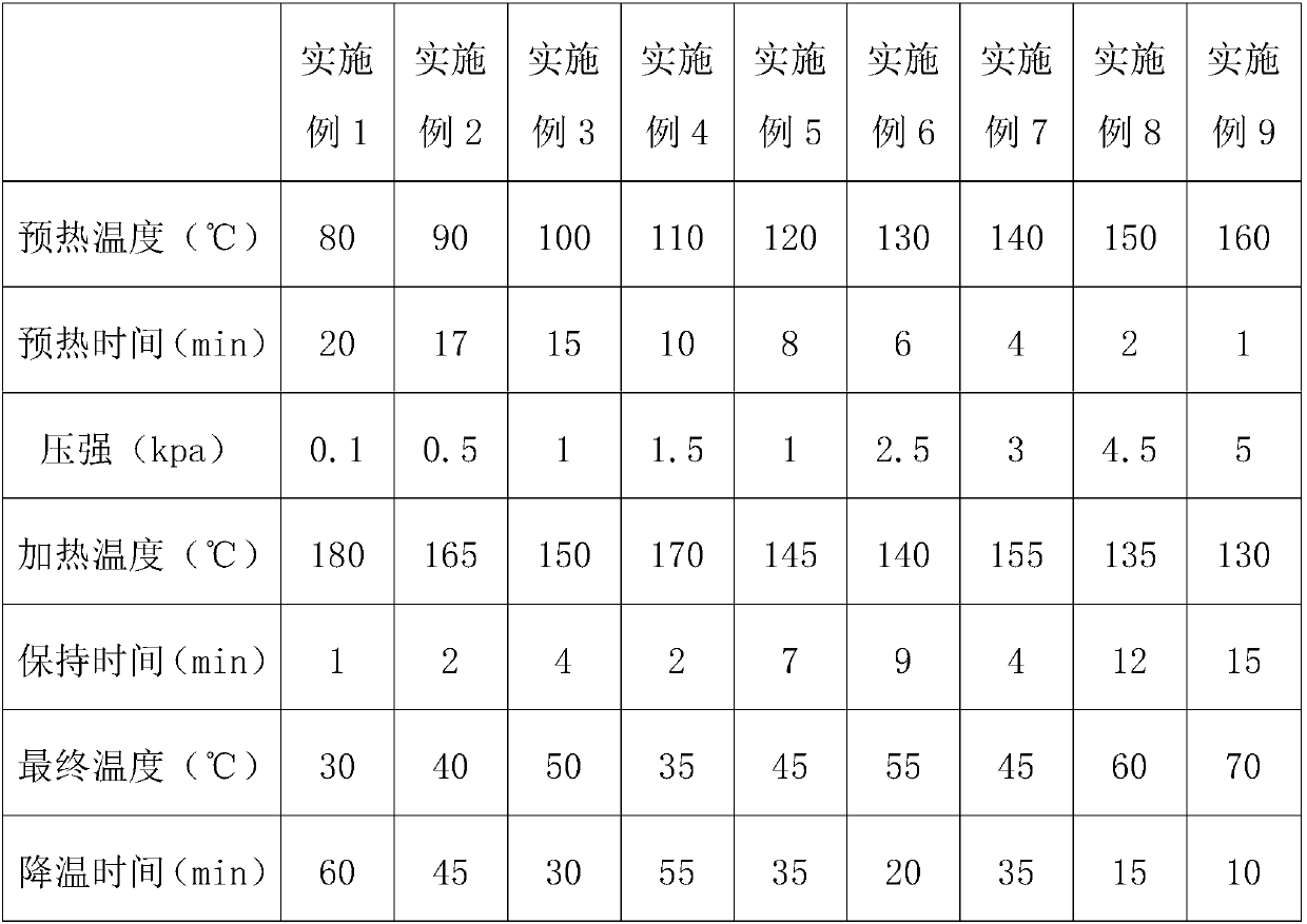
[0032] S2. Put the mold with the flat solar cell module fixed into the vacuum device, and then put the vacuum device into the cavity of the lamination device. In this embodiment, a lamination machine is selected, and then the vacuum device is preheated Operation, the preheating temperature and the preheating time of each embodiment are as shown in table 1.

[0033] S3. heat the laminator so that the temperature of the laminator remains within a certain range, and the temperature of the laminator is as shown in Table 1.

[0034] S4. Use a vacuum device to pressurize the planar solar cell assembly and maintain it for a period of time to perform lamination. The pressure and lamination time of the planar solar cell assembly are shown in Table 1.

[0035] S5. A...

Embodiment 10

[0039] This embodiment relates to a lamination method of a solar cell module. The difference between this embodiment and Embodiment 5 is that in this embodiment, a first positioning hole is provided on the mold, and a second positioning hole is provided on the planar solar panel assembly. , the first positioning hole and the second positioning hole are equipped with positioning pins. When fixing the planar energy component, first align the first positioning hole and the second positioning hole, and then insert the positioning pins into the first positioning hole and the second positioning hole at the same time , and finally use adhesive tape to fix the planar solar cell module on the mold.


PUM


Abstract

The invention relates to the field of solar cell panel preparation, in particular to a lamination method of a solar cell module and the solar cell module. The lamination method comprises the followingsteps: fixing a planar solar cell module on a mold, and then sequentially performing preheating and heating lamination operation to obtain the solar cell module. According to the invention, the solarcell module is obtained by laminating the planar solar cell module; in the laminating process, only the temperature needs to be reduced to soften the assembly. glue film does not need to be melted, and therefore, the situation that the melted glue film flows on the mold with a curved surface and is not uniformly distributed is avoided, and the yield is improved; and secondly, a preheating step isset, so that the planar solar cell module has an advanced softening process, and the situation that the glue film is extruded or broken due to the fact that the planar solar cell module is suddenly stressed during lamination is avoided.

Description

technical field [0001] The invention relates to the field of preparation of solar cell panels, in particular to a lamination method of a solar cell assembly and a solar cell assembly. Background technique [0002] With the development of solar cell technology, more and more solar cell components are used in various scenarios, for example, solar power backpacks, solar power mobile power supplies, car sunroofs, and the like. As the application scenarios of solar cell components increase, it means that there are more requirements for the shape of solar cell components, such as the need for solar cell components to form a curved surface structure. [0003] The structure of the existing solar cell assembly includes: a front plate, an adhesive film, a solar chip, an adhesive film and a back plate. However, in the prior art, solar cell modules with curved surface structures are mostly laminated and directly formed, that is, multi-layer encapsulation materials are bonded together, ...

Claims


Application Information

Patent Timeline
IPC IPC(8): B32B37/10B32B37/06H01L31/048
CPCB32B37/10B32B37/06H01L31/0481B32B2457/10B32B2457/12Y02E10/50
Inventor 程晓龙顾鸿扬刘磊
Owner 东君新能源有限公司
Why Eureka
Try Eureka