Full-life-cycle intelligent monitoring gas density relay and implementation method thereof

A technology with full life cycle and gas density, applied in the power field, can solve problems such as flashover, performance degradation, and affecting the reliable operation of electrical equipment

Pending Publication Date: 2020-07-24
SHANGHAI ROYE ELECTRICAL CO LTD
View PDF0 Cites 1 Cited by
  • Summary
  • Abstract
  • Description
  • Claims
  • Application Information

AI Technical Summary

Problems solved by technology

3) When the temperature drops, too much moisture may form condensation water, which will significantly reduce the insulation strength of the surface of the insulating part, or even flashover, causing serious damage
3) The perfo

Method used


Image

  • Full-life-cycle intelligent monitoring gas density relay and implementation method thereof
  • Full-life-cycle intelligent monitoring gas density relay and implementation method thereof
  • Full-life-cycle intelligent monitoring gas density relay and implementation method thereof

Examples


Embodiment 1

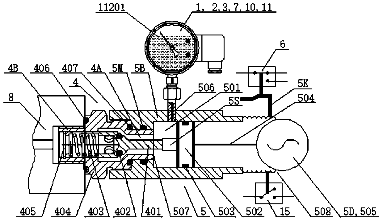
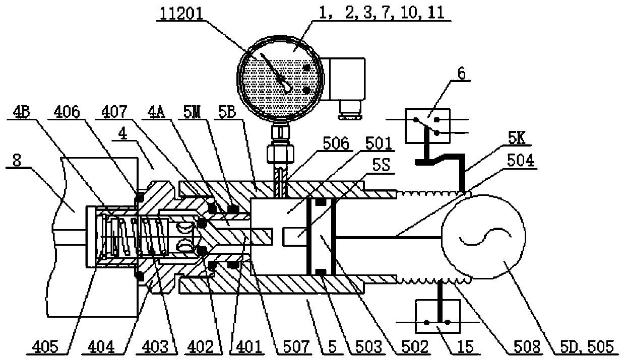
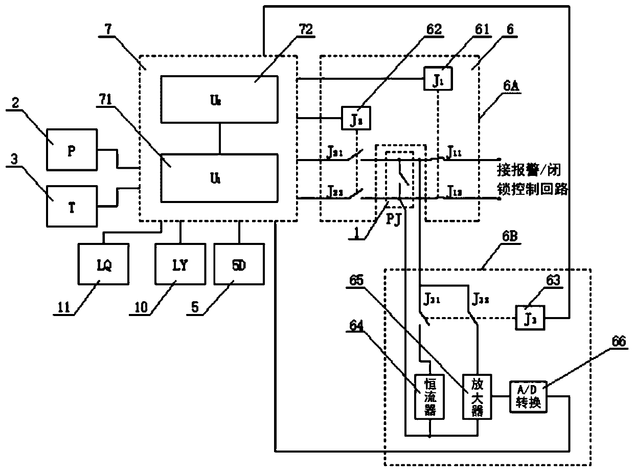
[0139] Figure 1 ~ Figure 2 It is a schematic structural diagram of a gas density relay used for high and medium voltage electrical equipment and intelligently monitored throughout its life cycle according to an embodiment of the present invention. The gas density relay for intelligent monitoring of the whole life cycle includes: the gas density relay body containing anti-vibration oil, the online calibration unit (including the pressure sensor 2, the temperature sensor 3, the valve 4, the pressure regulating mechanism 5, and the online calibration contact signal sampling Unit 6), intelligent control unit 7, oil leakage diagnosis detector 10, sealing performance detection unit 11 and contact resistance detection unit 6B. Among them, the gas density detection sensor (pressure sensor 2, temperature sensor 3), the intelligent control unit 7, the oil leakage diagnosis detector 10 and the sealing performance detection unit 11 are all set on the gas density relay body 1, and the conta...

Embodiment 2

[0172] Image 6 It is a schematic structural diagram of a gas density relay body used for high and medium voltage electrical equipment and intelligently monitored throughout its life cycle in the second embodiment of the present invention.

[0173] The difference between this embodiment and the first embodiment is:

[0174] The oil leakage diagnostic detector 10 of this embodiment is mainly composed of a video camera (or camera). The camera includes a camera body 1001 and a camera shield 1002. The camera is arranged outside the gas density relay body 1 (or inside the body). The principle is: the camera obtains the information of the gas density relay through image recognition technology, including oil leakage, water ingress, rust, foreign matter intrusion, blurred dial, rubber aging, rubber fracture, device damage, device falling, device jamming One or more of them, the intelligent control unit 7 or the background sends an oil leakage performance alarm signal or / and information. ...

Embodiment 3

[0179] Figure 7 It is a schematic structural diagram of a gas density relay body used for high and medium voltage electrical equipment and intelligently monitored throughout its life cycle in the third embodiment of the present invention.

[0180] The difference between this embodiment and the first embodiment is:

[0181] The sealing performance detection unit 11 is an SF6 diagnostic sensor 1101, and the SF6 diagnostic sensor 1101 may be arranged in the housing 102 of the gas density relay 1; or, the sealing performance detection unit 11 may also include a gas hood (or a leaking gas collector). ) 1102, the gas hood 1102 is arranged on the outside of the gas density relay body 1, and communicates with the housing 102 of the gas density relay body 1, forming a relatively sealed cavity (the SF6 diagnostic sensor and its bottom are required to be sealed , Can collect the leaked SF6 gas, that is, the upper part of the SF6 diagnostic sensor in the cavity may not be completely sealed). ...


PUM


Abstract

The invention provides a full-life-cycle intelligent monitoring gas density relay and an implementation method thereof. The gas density relay comprises a gas density relay body, an online verificationunit, an oil leakage diagnosis detector and an intelligent control unit. The on-line verification unit detects a contact signal action value and/or a contact signal return value of the gas density relay body; the oil leakage diagnosis detector is used for collecting oil leakage information of the gas density relay body; and the intelligent control unit or/ a background diagnoses the received and/or calculated contact signal action value and/or contact signal return value of the gas density relay body and the data or/and information monitored by the oil leakage diagnosis detector to obtain a current contact condition or/and oil leakage condition of the gas density relay body. The relay and the method are used for intelligently monitoring the whole life cycle of the gas density relay, guarantee safety of a power grid, guarantee safe operation of a power grid, do not need maintenance, improve efficiency, reduce operation and maintenance cost, and greatly improve the benefits of the powergrid.

Description

Technical field [0001] The invention relates to the field of electric power technology, in particular to a gas density relay for intelligent monitoring of the whole life cycle applied to high-voltage and medium-voltage electrical equipment and an implementation method thereof. Background technique [0002] At present, SF6 (sulfur hexafluoride) electrical equipment has been widely used in the power sector, industrial and mining enterprises, and has promoted the rapid development of the power industry. In recent years, with the rapid economic development, the capacity of my country's power system has expanded rapidly, and the consumption of SF6 electrical equipment has increased. The role of SF6 gas in high-voltage electrical equipment is arc extinguishing and insulation. If the density of SF6 gas in high-voltage electrical equipment is reduced and the content of micro water exceeds the standard, it will seriously affect the safe operation of SF6 high-voltage electrical equipment: ...

Claims


Application Information

Patent Timeline
IPC IPC(8): H01H35/26H01H35/38G01M3/04G01M3/20G01M3/26G01N9/00G01R31/327
CPCG01M3/04G01M3/20G01M3/26G01N9/00G01N9/002G01N2009/006G01R31/3274G01R31/3275H01H35/26H01H35/38
Inventor 金海勇夏铁新郭正操郝彩侠金海生
Owner SHANGHAI ROYE ELECTRICAL CO LTD
Why Eureka
Try Eureka