Connection structure of porous surface structure and substrate, preparation method and prosthesis

A technology of surface structure and porous structure, which can be used in prosthetics, medical science, joint implants, etc., and can solve problems such as the sharp decline in the mechanical properties of the substrate

Active Publication Date: 2020-07-28
YBNX MEDICAL TECH SUZHOU CO LTD
View PDF13 Cites 6 Cited by
  • Summary
  • Abstract
  • Description
  • Claims
  • Application Information

AI Technical Summary

Problems solved by technology

[0005] Based on the above reasons, it is necessary to develop a method that can not only improve the bonding strength between the porous structure and the substrate, but also avoid the substantial decline in the mechanical properties of the substrate caused by hot pressing processes (such as penetration welding processes).

Method used


Image

  • Connection structure of porous surface structure and substrate, preparation method and prosthesis
  • Connection structure of porous surface structure and substrate, preparation method and prosthesis
  • Connection structure of porous surface structure and substrate, preparation method and prosthesis

Examples


Embodiment 1

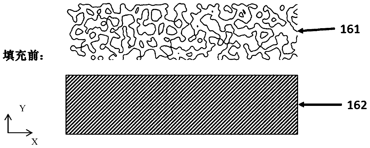
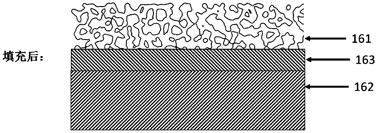
[0258] Figure 2a and Figure 2b They are schematic diagrams of the structure of the porous surface structure and the substrate before filling and after filling in Example 1, respectively. Figure 2a The positive direction of the X-axis shown in , represents the right, the negative direction of the X-axis represents the left, the positive direction of the Y-axis represents the top, and the negative direction of the Y-axis represents the bottom. To describe the technical solution of the present invention, the above-mentioned orientation regulations are only used to represent illustrations, and do not affect the orientation in practical applications.

[0259] The base 162 is solid, which is conducive to the overall strength of the connection structure, such as Figure 2a and Figure 2bshown. Alternatively, the substrate is another porous structure and the porosity of the substrate is less than that of the porous surface structure (not shown). The base 162 can be made of met...

Embodiment 1

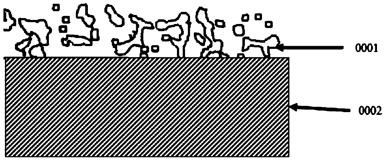
[0262] With regard to Embodiment 1, the above-mentioned scheme has defects: due to the formation of some multi-directional penetration, regular or irregular pores between the supports (or beams) of the porous surface structure 161, when the polymer material 163 is injected to fill the porous surface structure During the pore process of 161 , part of the polymer material is likely to permeate until it exceeds the top of the porous surface structure 161 , which will greatly affect the appearance and other performance (such as bone ingrowth) of the surface of the porous surface structure 161 .

[0263] In order to solve the above problems, the connection structure in the second embodiment is provided with a porous surface structure 171 in the high-porosity region (the porous surface structure 171 is also referred to as the first porous structure 171), and a second porous structure in the low-porosity region. Structure 172 (as a spacer layer) and substrate 173, the second porous st...

Embodiment 3

[0270] As a modification of Embodiment 2, such as Figure 4a and Figure 4b As shown in combination, in the third embodiment, the non-porous spacer plate 182 with a solid structure is used to replace the second porous structure 172 in the low-porosity region in the second embodiment above, that is, when the second porous structure in the second embodiment When the porosity is zero, it becomes the non-porous spacer 182 in the third embodiment. Similarly, the porous surface structure 181 in the third embodiment includes many struts (or beams) arranged in a staggered manner, and some multi-directional, regular or irregular pores are formed between these struts (or beams).

[0271] In some examples, the non-porous spacer plate 182 may be disposed at any cross-sectional position between the top and the bottom of the porous surface structure 181 .

[0272] Exemplarily, the direction in which the non-porous spacer plate 182 is embedded into the porous surface structure 181 (for exa...


PUM


Abstract

The invention discloses a connection structure of a porous surface structure and a substrate, a preparation method and a prosthesis. A high polymer material layer is arranged in a gap between the porous surface structure and the substrate, so that the porous surface structure is tightly connected with the substrate, the basic strength of the connecting structure is ensured, the stress shielding phenomenon is improved, and the problem of postoperative osteolysis is solved; wherein a pre-connected complex is arranged on the substrate, the pre-connected complex comprises another porous structureand an intermediate which are connected in advance, the pre-connected complex and the substrate are combined in advance through various methods, and then the substrate with the pre-connected complex is tightly connected with the porous surface structure through a high polymer material layer. Relative movement and even falling between a structure body formed by the high polymer material layer and the porous structure on the surface of the high polymer material layer and the substrate with a smooth surface can be prevented; on the basis of the surface of the porous structure, it can be guaranteed that the surface of the artificial implant prosthesis has excellent bone ingrowth performance, the strength of the substrate is not substantially affected, and the rigidity of the overall compositestructure is optimized to reduce the stress shielding risk.

Description

technical field [0001] The invention relates to a connection technology of a mechanical structure, in particular to a medical device, and provides a connection structure, a preparation method and a prosthesis of a porous surface structure and a substrate. Background technique [0002] Engineering applications often have different requirements on the overall performance and surface performance of mechanical structures. For example, the overall performance (such as fatigue strength) of the acetabular cup and femoral stem of the artificial hip joint must meet the dynamic load that the prosthesis bears when it is implanted in the body for decades, with an average of one million to two million walks per year In addition, there are specific performance requirements for the surface of the prosthesis, so as to meet the firm combination of the surface of the prosthesis and the patient's bone group and ensure that the prosthesis does not loosen; otherwise, the patient will have pain, ...

Claims


Application Information

Patent Timeline
Patent Type & Authority Applications(China)
IPC IPC(8): A61F2/30A61L27/14A61L27/50
CPCA61F2/34A61F2/36A61F2/30942A61F2002/30011A61F2002/3092A61F2002/30985B33Y80/00A61F2002/3093A61F2002/30971A61F2310/00796A61F2002/30014A61C8/00A61F2/32A61F2/38A61F2/40A61F2/42A61F2/44A61F2002/30052A61F2002/30451A61F2002/30967A61F2002/3097A61F2002/30973A61F2/3094A61F2/30767A61C8/0012A61C8/0013Y02E60/50Y02P10/25A61F2/30771A61F2/3662A61F2/3859A61F2/389A61F2002/3006A61F2002/30324A61F2002/30329A61F2002/30772A61F2002/3863B23K11/11B23K11/14B23K11/16
Inventor 姚建清史金虎
Owner YBNX MEDICAL TECH SUZHOU CO LTD
Why Eureka
Try Eureka