Spiral steel pipe end welding line coping and polishing robot

A spiral steel pipe and robot technology, applied in surface polishing machine tools, grinding/polishing equipment, grinders, etc., can solve the problems of low grinding efficiency, high grinding wheel replacement cost, insufficient grinding accuracy, etc., and achieve smooth and smooth grinding surface. , The effect of high machine power utilization and low replacement cost

Active Publication Date: 2020-07-28
宝鸡宇喆工业科技有限公司
View PDF4 Cites 5 Cited by
  • Summary
  • Abstract
  • Description
  • Claims
  • Application Information

AI Technical Summary

Problems solved by technology

[0003] However, under the existing technology, the equipment on the market that directly carries the grinding head with the help of a manipulator to complete the automatic grinding generally has insufficient grinding accuracy, which leads to the need for manual secondary grinding or damage to the base metal of the welded pipe after grinding because the weld bead reinforcement is too high Leading to the scrapping of steel pipes, that is, it is impossible to achieve the fully automatic grinding accuracy and technical index requirements described above in line with the API Spec5L standard and the GBT97111-1997 standard.
[0004] Take a kind of robot polishing system with three-dimensional vision and its control method disclosed by the publication number CN109483369A, and a kind of robot polishing system and its control method with three-dimensional vision disclosed by the publication number CN109483369A as an example: the above two technical solutions are Pneumatic grinding technology is adopted; although it has certain advantages in flexible output; however, affected by the compressibility of gas, the gas in the pneumatic actuator is easily fluctuated by changes in the external environment temperature, resulting in poor stability of the natural frequency of the pneumatic system, resulting in the final Grinding linearity output is not ideal
Not only that, the performance of the system is not stable due to the serious creeping effect of the cylinder friction of the pneumatic actuator at low speed, so the reliability of high-precision grinding is restricted
Therefore, it is impossible to meet the high-precision and reliable automatic grinding requirements of the weld bead spiral steel pipe end weld within 0.5mm height after high-precision smooth grinding without damaging the base material.
[0005] In addition, the publication number CN109483369A discloses a robot grinding system with three-dimensional vision and its control method. Since the multi-degree-of-freedom manipulator is used to directly carry the grinding wheel for grinding, due to the limitation of the accuracy of the motion track planning of the manipulator and the elastic deformation of the track sensors of each joint. The joints generate additional rotation angle increments, and the displacement generated by the rotation angle increments will be amplified by the arm length of each execution unit of the multi-degree-of-freedom manipulator. Therefore, the grinding accuracy of the multi-degree-of-freedom manipulator directly carrying the grinding head is limited and cannot completely replace manual grinding. Achievable technical requirements
In addition, the grinding wheel is only used for grinding; the grinding wheel and the weld seam of the steel pipe are ground in point contact, the grinding efficiency is low, the replacement cost of the grinding wheel is high, and the power utilization rate of the machine tool is not ideal

Method used


Image

  • Spiral steel pipe end welding line coping and polishing robot
  • Spiral steel pipe end welding line coping and polishing robot
  • Spiral steel pipe end welding line coping and polishing robot

Examples


Embodiment Construction

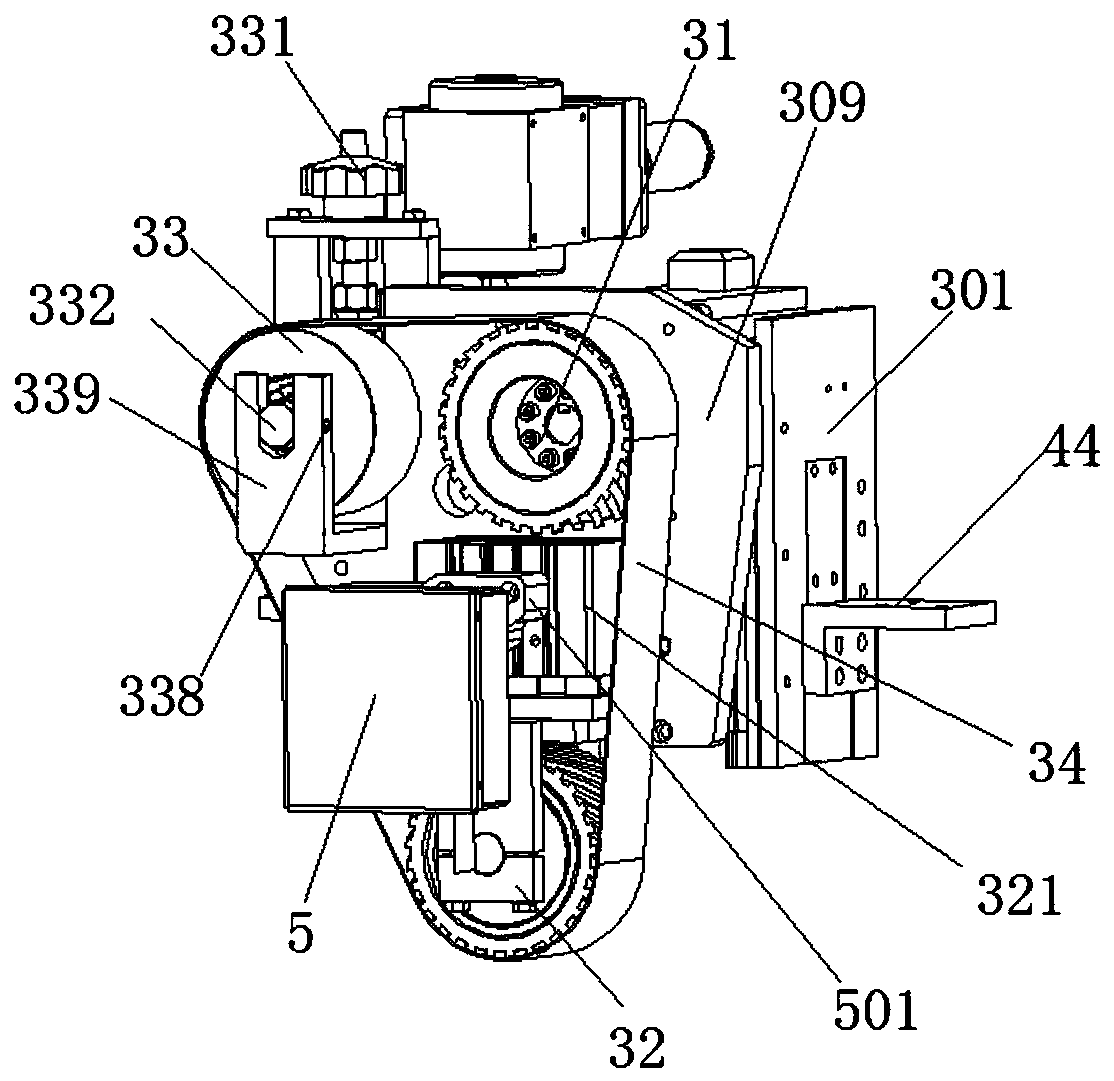
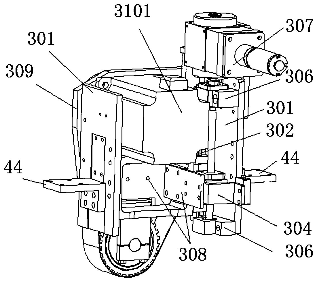
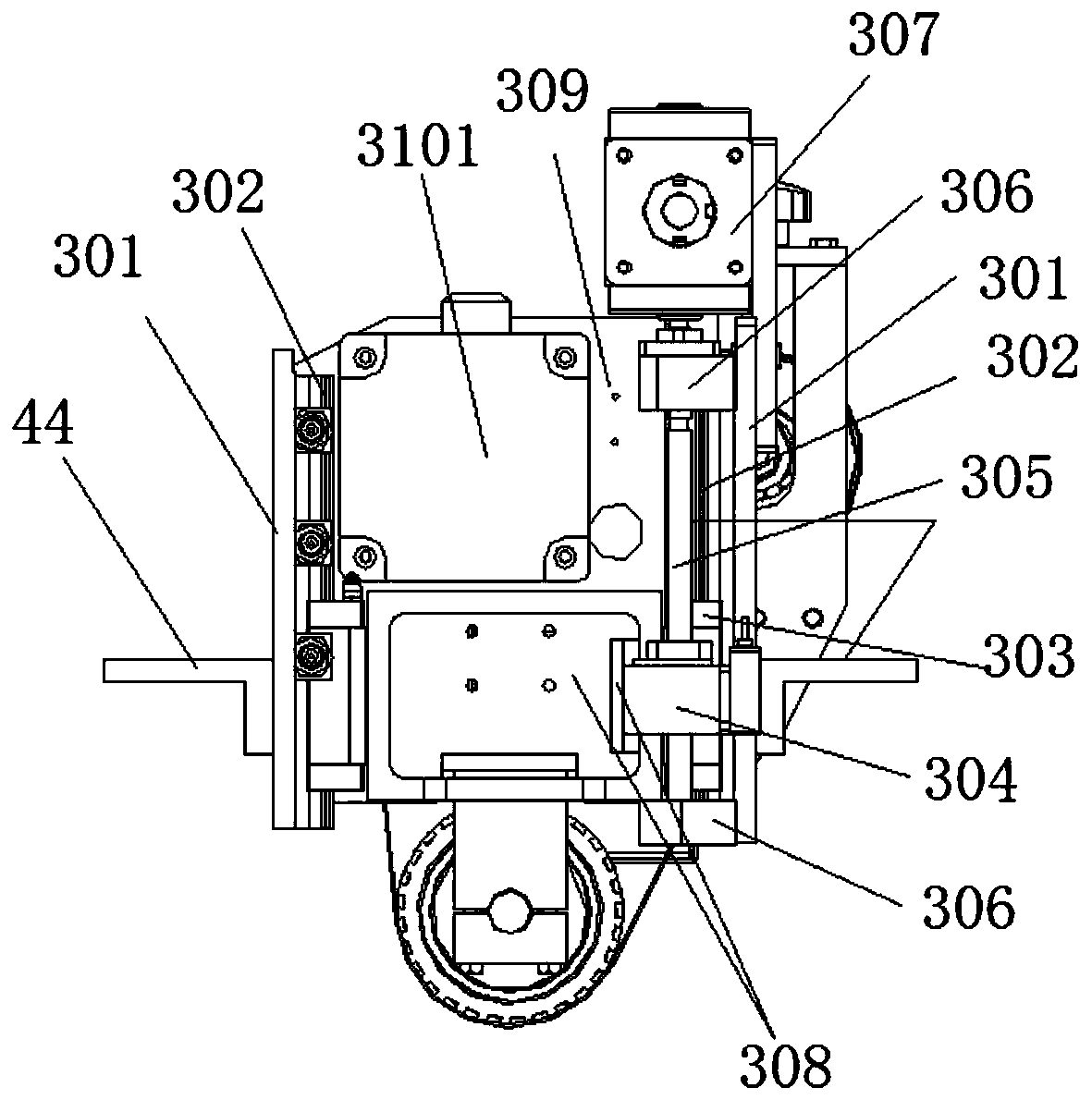
[0056] Attached below Figure 1-25 Specific examples of the present invention are described. It should be understood that the embodiments described below are only illustrative rather than specific limitations on the present invention.

[0057] The following examples facilitate a better understanding of the present invention, but do not limit the present invention. The experimental methods in the following examples are conventional methods unless otherwise specified. The components and materials used in the following examples are commercially available unless otherwise specified. The implementation of the control circuit in the following embodiments is a conventional control method unless otherwise specified.

[0058] In the present invention, unless stated otherwise, it should be understood that the terms "center", "upper", "lower", "front", "rear", "left", "right", "vertical The orientations or positional relationships indicated by "straight", "horizontal", "top", "bottom...


PUM


Abstract

The invention provides a spiral steel pipe end welding line coping and polishing robot. A two-freedom-degree fine grinding executing mechanism provided with a laser outline instrument is arranged at the executing end of a multi-freedom-degree mechanical arm, the grinding precision and the polishing precision of the mechanical arm are improved while motion control is simplified, and the technical problems that the quality of a welding bead at the pipe end of a spiral steel pipe ground through a multi-freedom-degree grinding mechanical arm in the prior art cannot meet the technology index requirements regulated by the API Spec5L standard and the GBT97111-1997 standard; and manual secondary coping is still needed are solved. The spiral steel pipe end welding line coping and polishing robot can be used for spiral steel pipe outer welding line grinding and is suitable for spiral steel pipe inner welding line grinding, and base metal is not damaged during coping; after coping, the remnant height can be smaller than or equal to 0.1 mm to the minimum and is far higher than the requirements of the API Spec5L standard and the GBT97111-1997 standard; and the laser outline instrument cooperates with a special detection algorithm, and high-precision scanning detection for precision smaller than 0.05 mm can be achieved; and the powerful technology support is provided for high-precision welding line coping.

Description

technical field [0001] The invention belongs to the technical field of operation transportation grinding and polishing, and in particular relates to a welding seam repairing and polishing robot at the end of a spiral steel pipe. Background technique [0002] Spiral steel pipe is a pipe made of strip steel coil as raw material and rolled by spiral welding process. For the spiral steel pipe, in order to meet the welding quality of the next step of the steel pipe butt girth welding of the spiral steel pipe end, the API Spec5L standard and the GBT97111-1997 standard both clearly stipulate: Take the weld seam of the spiral steel pipe end with a diameter of 508mm as an example: First, The weld reinforcement within the length range of at least 150mm from the pipe end of the spiral welded pipe should be removed, that is, the requirements for the axial grinding elongation of the pipe end of the spiral steel pipe should be removed; secondly, the weld bead after grinding should not be ...

Claims


Application Information

Patent Timeline
Patent Type & Authority Applications(China)
IPC IPC(8): B24B21/16B24B21/18B24B21/20B24B29/08B25J11/00
CPCB24B21/16B24B21/18B24B21/20B24B29/08B25J11/0065
Inventor 张瑾宇王林军刘伟马利刘晨
Owner 宝鸡宇喆工业科技有限公司
Why Eureka
Try Eureka