
Double-beam laser heating auxiliary drilling integration device and method

A laser heating and integrated device technology, applied in the direction of stone processing tools, stone processing equipment, work accessories, etc., can solve the problem of insignificant improvement in processing efficiency and processing quality, incapable of high efficiency and low damage ultra-hard and brittle materials, hole entrance and exit It is easy to have problems such as chipping, so as to achieve the effects of reducing processing costs, easy control, and improving processing efficiency

Pending Publication Date: 2020-07-31
SHENYANG AEROSPACE UNIVERSITY
View PDF0 Cites 4 Cited by
  • Summary
  • Abstract
  • Description
  • Claims
  • Application Information

AI Technical Summary

Problems solved by technology

[0003] With the development of modern manufacturing industry, there are more and more applications of new materials and complex parts of difficult-to-machine materials. Heating-assisted cutting technology can effectively solve the cutting process of difficult-to-machine materials. However, the single laser heating-assisted cutting technology of laser heating The induced temperature field is difficult to fully soften the processed material, and the processing efficiency and processing quality are not significantly improved, making it impossible to process ultra-hard and brittle materials with high efficiency and low damage, especially the emerging ceramics and glass
For transparent and difficult-to-machine materials, such as aluminum oxynitride (AlON) transparent ceramics, neodymium-doped yttrium-aluminum garnet, magnesium-aluminum spinel, glass and other ultra-hard and brittle materials, when drilling complex parts of these difficult-to-machine materials, the Drilling tool wear is very serious, the hole entrance and exit are prone to defects such as edge chipping, and the processing efficiency is low and the cost is high

Method used


Image

  • Double-beam laser heating auxiliary drilling integration device and method
  • Double-beam laser heating auxiliary drilling integration device and method
  • Double-beam laser heating auxiliary drilling integration device and method

Examples


Embodiment Construction

[0045] The following will clearly and completely describe the technical solutions in the embodiments of the present invention with reference to the accompanying drawings in the embodiments of the present invention. Obviously, the described embodiments are only part of the embodiments of the present invention, not all of them.

[0046] In describing the present invention, it should be understood that the terms "longitudinal", "transverse", "vertical", "upper", "lower", "front", "rear", "left", "right", The orientation or positional relationship indicated by "vertical", "horizontal", "top", "bottom", "inner", "outer", etc. is based on the orientation or positional relationship shown in the drawings, and is only for the convenience of describing the present invention and Simplified descriptions, rather than indicating or implying that the device or element referred to must have a particular orientation, be constructed and operate in a particular orientation, and thus should not be...


PUM


Abstract

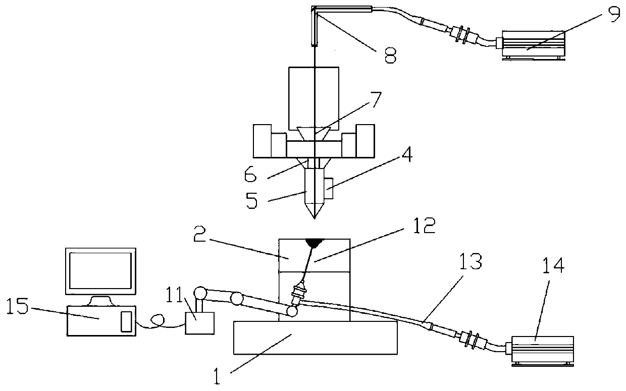
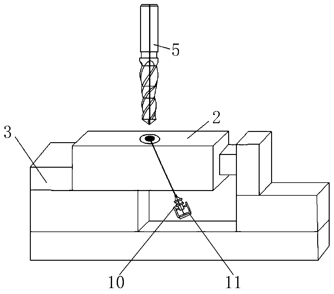
The invention provides a double-beam laser heating auxiliary drilling integration device and method, and belongs to the technical field of machining. The double-beam laser heating auxiliary drilling integration device comprises a continuous laser generation system and a pulse laser generation system, wherein the continuous laser generation system comprises a continuous laser generator and a continuous laser focusing head; a manipulator clamps the continuous laser focusing head to move so as to adjust the irradiation direction of a continuous laser beam, the size of a laser spot, the laser movement speed and the distance between the center of the laser spot and the surface of a workpiece; the pulse laser generation system comprises a pulse laser generator and a collimation system which areconnected with each other; and the pulse laser beam irradiates the surface of the workpiece from the interior of a drill bit along a drill tip through the collimation system. Compared with single-beamlaser heating, the double-beam laser heating auxiliary drilling integration device and method have higher machining efficiency and lower surface damage, drilling machining of transparent materials difficult to machine is realized, and the cost is reduced.

Description

technical field [0001] The invention relates to the technical field of mechanical processing, in particular to an integrated device and method for dual-beam laser heating-assisted drilling. Background technique [0002] Laser heating assisted cutting technology is to focus a high-power laser beam on the surface of the workpiece in front of the cutting edge. In a short time before the material is cut, the local heating is heated to a very high temperature to change the machinability of the material at high temperature, and then Use conventional tools for processing. By heating the material in a small local area, the plasticity of the material is improved while the hardness of the material is reduced, the cutting force is reduced, the service life of the tool is extended, the formation of surface damage is suppressed, and cutting chatter is prevented, so as to improve processing efficiency, reduce cost, The purpose of improving surface quality. For hard and brittle ceramics ...

Claims


Application Information

Patent Timeline
Patent Type & Authority Applications(China)
IPC IPC(8): B28D1/14B28D1/22B28D7/04B28D7/00
CPCB28D1/14B28D1/221B28D7/04B28D7/005
Inventor 孔宪俊王明海王奔郑耀辉马书娟
Owner SHENYANG AEROSPACE UNIVERSITY
Learn More