
A solid-liquid compound lubrication method for cup-type harmonic gear reducer

A gear reducer and harmonic technology, which is applied in the field of solid-liquid compound lubrication of cup type harmonic gear reducer

Active Publication Date: 2021-06-29
LANZHOU INST OF CHEM PHYSICS CHINESE ACAD OF SCI
View PDF8 Cites 0 Cited by
  • Summary
  • Abstract
  • Description
  • Claims
  • Application Information

AI Technical Summary

Problems solved by technology

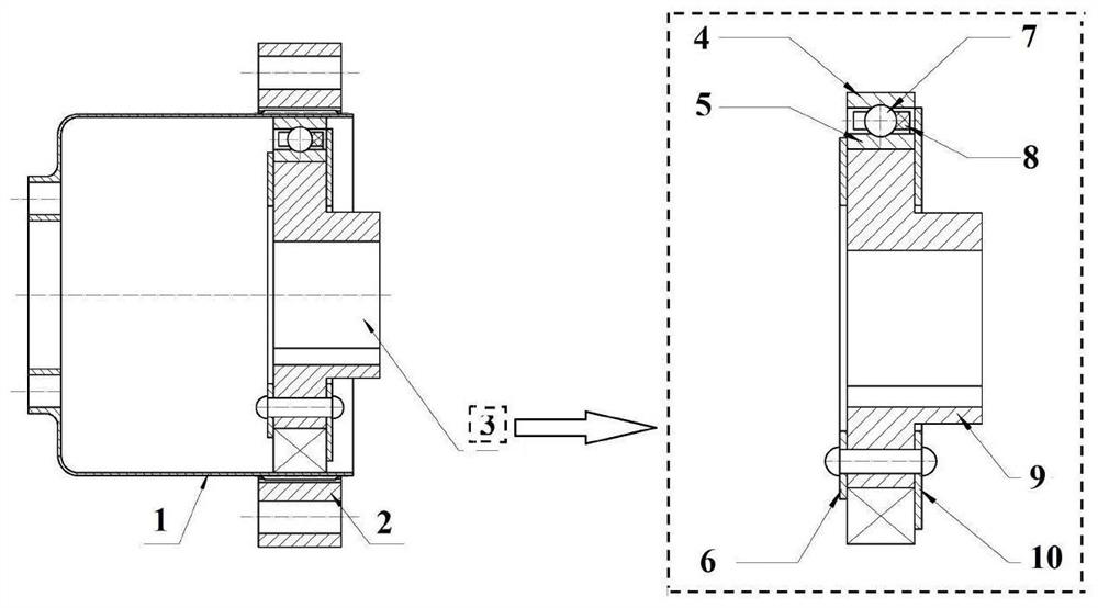
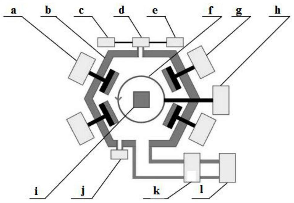
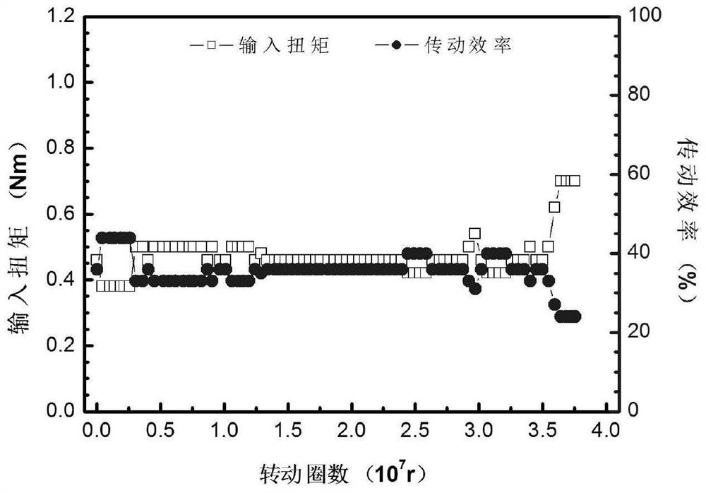
[0005] In view of this, the purpose of the present invention is to provide a solid-liquid composite lubrication method for cup-shaped harmonic gear reducers. The solid-liquid composite lubrication method provided by the present invention can effectively solve the problems caused by perfluoropolyether grease during friction The technical problem of its degradation caused by tribochemical reaction, and the good lubricating performance of lubricating grease can be used to prolong the lubrication life of cup type harmonic gear reducer

Method used


Image

  • A solid-liquid compound lubrication method for cup-type harmonic gear reducer
  • A solid-liquid compound lubrication method for cup-type harmonic gear reducer
  • A solid-liquid compound lubrication method for cup-type harmonic gear reducer

Examples


Embodiment 1

[0046] (1) After splitting the XB1-60-150 type cup-type harmonic gear reducer into rigid wheels, flexible wheels, flexible bearing inner rings, flexible bearing outer rings, flexible bearing steel balls, cams and baffles, the Ultrasonic cleaning was carried out in gasoline and acetone solution, and air-dried to obtain the components to be treated with solid lubrication.

[0047] (2) Matching clean gloves, load the rigid wheel, flexible wheel, flexible bearing inner ring and flexible bearing outer ring to be treated by solid lubrication on the workpiece rack of the coating vacuum chamber, close the door of the vacuum chamber, and turn on the mechanical pump and molecular pump in turn. The vacuum chamber is evacuated to a vacuum degree of 5.0×10 -3 Pa; turn on the argon valve and gas filling valve in turn, fill the vacuum chamber with argon until the partial pressure of argon in the vacuum chamber is maintained at 4Pa; turn on the DC bias power supply, adjust the DC bias value u...

Embodiment 2

[0060] The difference between this embodiment and embodiment 1 is that the transition layer and the deposition conditions of the composite film layer are different:

[0061] When the closed-field unbalanced magnetron sputtering method is used to prepare the Cr thin film layer and the WC thin film layer, the sputtering power of the corresponding Cr target and WC target is 4kW, the DC bias voltage is -50V, and the deposition time is 10min. , the rotation speed of the workpiece rack driving motor is 1r / min;

[0062] When plasma-assisted chemical vapor deposition is combined with closed-field unbalanced magnetron sputtering to prepare C-WC composite film layers, the sputtering power of the WC target is 2kW, the DC bias voltage is -500V, the deposition time is 80min, and the workpiece rack The rotation speed of the driving motor is 1r / min.

[0063] The carrying capacity of the C-WC composite film layer deposited on the rigid wheel, flexible wheel, flexible bearing inner ring and f...

Embodiment 3

[0067] The difference between this embodiment and embodiment 1 is only that the conditions of film deposition are different:

[0068] When the closed-field unbalanced magnetron sputtering method is used to prepare the Cr film layer and the WC film layer, the sputtering power of the corresponding Cr target and the WC target is 8kW, the DC bias voltage is -200V, and the deposition time is 20min. The rotation speed of the workpiece rack driving motor is 10r / min; when the plasma-assisted chemical vapor deposition is combined with the closed field unbalanced magnetron sputtering method to prepare the C-WC composite thin film layer, the sputtering power of the WC target is 4kW, and the DC bias The voltage is -700V, the deposition time is 90min, and the rotation speed of the workpiece rack driving motor is 10r / min.

[0069] The carrying capacity of the C-WC composite film layer deposited on the rigid wheel, flexible wheel, flexible bearing inner ring and flexible bearing outer ring o...


PUM

PropertyMeasurementUnit
thicknessaaaaaaaaaa
hardnessaaaaaaaaaa

Abstract

The invention provides a solid-liquid compound lubrication method for a cup-shaped harmonic gear reducer, and relates to the technical field of reducer lubrication. The solid-liquid composite lubrication method provided by the present invention comprises the following steps: using the closed field unbalanced magnetron sputtering method on the rigid wheel, flexible wheel, flexible bearing inner ring and flexible bearing outer of the cup-shaped harmonic gear reducer A transition layer is deposited on the surface of the circle; the transition layer includes a Cr thin film layer and a WC thin film layer from the inside to the outside; Utilize plasma-assisted chemical vapor deposition in combination with closed field unbalanced magnetron sputtering to deposit C-WC on the transition layer surface Composite film layer; sequentially coating perfluoropolyether lubricating oil and perfluoropolyether grease on the surface of the C-WC composite film layer. The solid-liquid composite lubrication method provided by the invention effectively solves the technical problem of the degradation of perfluoropolyether lubricating grease due to tribochemical reactions during friction, and prolongs the lubrication life of the cup-shaped harmonic gear reducer under vacuum environment conditions.

Description

technical field [0001] The invention relates to the technical field of lubrication of reducers, in particular to a solid-liquid composite lubrication method for a cup-shaped harmonic gear reducer. Background technique [0002] Harmonic gear reducers have technical characteristics such as large transmission ratio, high transmission precision, small size, and light weight, so they are widely used in the field of aerospace technology. Appropriate lubrication method is the key to achieve long life of cup type harmonic gear reducer in aerospace field. [0003] The lubrication methods of cup type harmonic gear reducer mainly include solid lubrication, liquid lubrication and solid-liquid composite lubrication. In contrast, solid lubrication has the advantages of simple structure, no need for sealing, and tribological properties are not sensitive to ambient temperature, but the disadvantage is that its life is relatively limited; liquid lubrication can achieve long-life lubrication...

Claims


Application Information

Patent Timeline
Patent Type & Authority Patents(China)
IPC IPC(8): C23C14/35C23C14/16C23C14/06C23C16/26C23C16/32C23C16/513F16H57/04
CPCC23C14/0635C23C14/165C23C14/35C23C16/26C23C16/32C23C16/513F16H57/041F16H57/0471F16H57/0482
Inventor 高晓明翁立军孙嘉奕胡明伏彦龙杨军王德生姜栋王琴琴
Owner LANZHOU INST OF CHEM PHYSICS CHINESE ACAD OF SCI
Learn More