Packaging structure of power MOSFET chip

A packaging structure and chip technology, applied in the direction of electrical components, electrical solid devices, circuits, etc., can solve the problems that the cellular structure bears large stress, cannot guarantee the pressure, and uniform distribution, so as to improve the compressive performance and reliability, retain Double-sided heat dissipation capability, the effect of preventing bending and breaking

Pending Publication Date: 2020-07-31
GLOBAL ENERGY INTERCONNECTION RES INST CO LTD
View PDF2 Cites 2 Cited by
  • Summary
  • Abstract
  • Description
  • Claims
  • Application Information

AI Technical Summary

Problems solved by technology

[0006] Therefore, the technical problem to be solved by the present invention is to overcome the fact that in the prior art, the crimp packaged chip cannot ensure the uniform distribution of pressure on the contact surface betw

Method used


Image

  • Packaging structure of power MOSFET chip
  • Packaging structure of power MOSFET chip
  • Packaging structure of power MOSFET chip

Examples


Embodiment Construction

[0034] The technical solutions of the present invention will be clearly and completely described below in conjunction with the accompanying drawings. Apparently, the described embodiments are some of the embodiments of the present invention, but not all of them. Based on the embodiments of the present invention, all other embodiments obtained by persons of ordinary skill in the art without making creative efforts belong to the protection scope of the present invention.

[0035]In the description of the present invention, it should be noted that the terms "center", "upper", "lower", "left", "right", "vertical", "horizontal", "inner", "outer" etc. The indicated orientation or positional relationship is based on the orientation or positional relationship shown in the drawings, and is only for the convenience of describing the present invention and simplifying the description, rather than indicating or implying that the referred device or element must have a specific orientation, o...


PUM

PropertyMeasurementUnit
Widthaaaaaaaaaa

Abstract

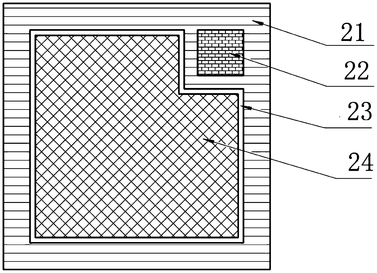
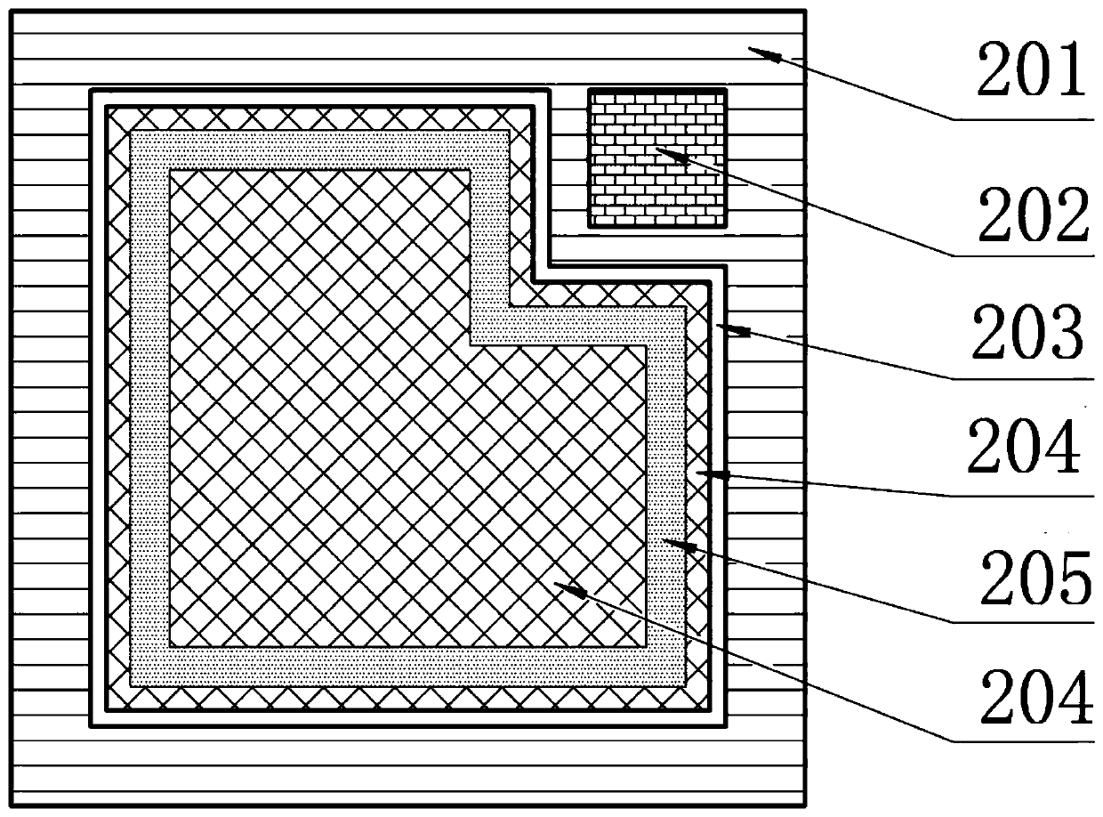
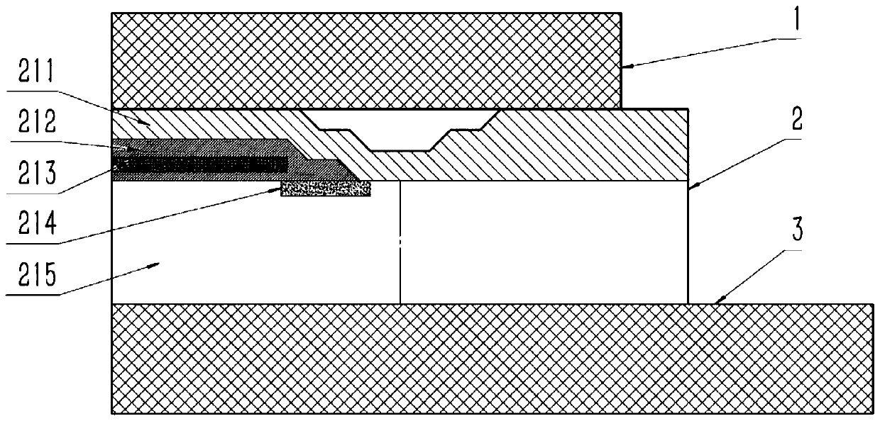
The invention discloses a packaging structure for a power MOSFET chip. The structure comprises the MOSFET chip which comprises a grid electrode and a source electrode on the front surface and a drainelectrode on the back surface, a first electric conductor which is electrically connected with the drain electrode on the back surface of the MOSFET chip, and a second electric conductor which is electrically connected with the source electrode on the front surface of the MOSFET chip through crimping packaging. A stress buffer area is arranged in the area, occupying the front surface of the MOSFETchip, of the source electrode, and the edge, making contact with the source electrode, of the second electric conductor is located in the stress buffer area. The part, corresponding to the stress buffer area, of the MOSFET chip does not contain a cellular structure. By additionally arranging the stress buffer area on the source electrode of the MOSFET chip, the damage of the edge stress concentration of the second electric conductor to the cellular structure in the MOSFET chip can be remarkably reduced, and the compression resistance and the reliability of the MOSFET chip are greatly improved. Meanwhile, the double-sided heat dissipation capacity is reserved, which improves the power level of a device.

Description

technical field [0001] The invention relates to the technical field of semiconductor packaging, in particular to a packaging structure of a power MOSFET chip. Background technique [0002] At present, high-power MOSFET devices can be divided into soldering type and crimping type according to the packaging process. The common welding type power MOSFET packaging structure mainly includes busbar electrodes, bonding wires, chips, soldering layers, lining boards and substrates. key link. In order to improve the reliability of the device, it is required that the coefficients of thermal expansion of each part of the material match, the heat dissipation characteristics are good, and the connection interface is as few as possible and the connection is firm. As the power level continues to increase, under the constraints of welding, wire bonding and other process conditions, the failure problems such as chip soldering layer degradation and lead shedding in the soldered structure are...

Claims


Application Information

Patent Timeline
IPC IPC(8): H01L29/78H01L29/16H01L29/06H01L23/367
CPCH01L29/78H01L29/0692H01L29/0638H01L29/1608H01L23/3672
Inventor 林仲康汤广福吴军民金锐唐新灵韩荣刚王亮杜玉杰周扬
Owner GLOBAL ENERGY INTERCONNECTION RES INST CO LTD
Why Eureka
Try Eureka