Solid-liquid separation and vibrating liquid-removing drying integrated device

A solid-liquid separation and deliquoring technology, which is applied in drying solid materials, filtration separation, separation methods, etc., can solve the problems of a large ungrounded processing system, unattainable moisture content, and drilling cuttings pulling requirements, etc., and achieves low manufacturing costs. , The effect of low moisture content of drilling cuttings and quick installation

Pending Publication Date: 2020-08-04
中石化石油工程技术服务有限公司 +3
View PDF0 Cites 3 Cited by
  • Summary
  • Abstract
  • Description
  • Claims
  • Application Information

AI Technical Summary

Problems solved by technology

[0003] At present, most of the first-stage solid-liquid separation equipment in the solid control system used by the well team is a triple-network shale shaker, which only performs preliminary solid-liquid separation for the solid-liquid mixture in the wellbore, and the separation ability is relatively weak, especially for drilling in the upper formation. When the displacement of the pump is relatively large, it is easy to paste the sieve and run out of slurry. The moisture content of the drill cuttings discharged after the solid-liquid separation of the vibrating screen cannot meet the requirements for drilling cuttings transportation. It is necessary to connect a vibrating screen or add more sets of equipment in series. Deliquoring and drying the discharged drill cuttings, resulting in a large and complex drilling fluid solid phase control and non-landing treatment system, which occupies a large area, high manufacturing cost, and high energy consumption

Method used


Image

  • Solid-liquid separation and vibrating liquid-removing drying integrated device
  • Solid-liquid separation and vibrating liquid-removing drying integrated device

Examples


Embodiment Construction

[0019] The present invention will be further described in detail below in conjunction with the drawings and specific embodiments.

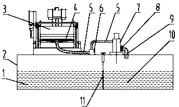
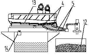
[0020] See figure 1 , figure 2 An integrated device for solid-liquid separation and vibration de-liquid drying, comprising a liquid-phase collection bin 1, a drilling fluid circulation tank 2, a vibrating screen 3, a suction cup 4, a liquid inlet pipe 5, a tee 6, a vacuum pump 7, a control valve 8. The liquid outlet pipe 9, the liquid phase collection bin 10, the partition 11, the drill cuttings collection bin 12, the screen 13, and the flapper valve 14.

[0021] The vibrating screen 3 adopts a two-stage plate screen 13 installed on the surface of the drilling fluid circulation tank 2. The bottom of the first stage screen 13 is directly connected to the drilling fluid circulation tank 2, and the second stage screen 13 is close to the slag discharge port. A suction cup 4 is installed below, and the suction cup 4 and the screen 13 are installed in a s...


PUM


Abstract

The invention provides a solid-liquid separation and vibrating liquid-removing drying integrated device, and the device comprises a liquid phase collection storehouse, a drilling fluid circulating pot, a vibrating screen, a sucking disc, a liquid inlet pipe, a tee joint, a vacuum pump, a control valve, a liquid outlet pipe, a clapboard, a drilling cuttings collection storehouse, a screen cloth anda gate valve. Mechanical vibration and vacuum adsorption principles are used for the device, thus, solid phase moisture content of a solid-liquid mixture returned up from a shaft bottom is reduced after the solid-liquid mixture is subjected to solid-liquid separation and liquid-removing drying by the vibrating screen, thus, the solid-liquid mixture meets rock debris transportation requirements, pollution to environment caused by waste generated in a drilling process is reduced effectively, and the recycled drilling fluid is collected for cycle use in the drilling fluid circulating pot. The device has the advantages of being simple in structure, needing low energy consumption, being convenient to use, being mounted quickly, having high equipment reliability, needing low manufacturing costand occupying small area; moisture content of the treated drilling cuttings is not more than 60%, and the drilling cuttings meet drilling cuttings transportation reequipments; and the device is used for a drilling fluid solid phase control and no-landing integrated treatment system, and simplifies system constitution.

Description

Technical field [0001] The invention relates to the technical field of petroleum drilling equipment, in particular to an integrated solid-liquid separation and vibration de-liquid drying device suitable for an integrated treatment system for solid phase control and non-grounding of drilling fluid. Background technique [0002] With the increasing depth, difficulty, and complexity of petroleum exploration and development, safety, environmental protection, and health management requirements are becoming more and more stringent. The requirements for solid phase control and environmental treatment of drilling fluids are getting higher and higher, and the whole process of drilling is required. To realize that the drilling fluid and discarded drill cuttings do not fall to the ground, the drill cuttings separated during the solid phase control of the drilling fluid need to be collected and transported away from the well site, which effectively reduces the environmental pollution of the w...

Claims


Application Information

Patent Timeline
Patent Type & Authority Applications(China)
IPC IPC(8): E21B21/06B01D33/03B01D33/41F26B11/18F26B25/00
CPCB01D33/0353B01D33/41E21B21/066F26B11/181F26B25/00
Inventor 董怀荣李琴郭振陈志礼李亚伟高煜李忠新崔海林李作会
Owner 中石化石油工程技术服务有限公司
Why Eureka
Try Eureka