10nm-level particle detection device and method applied to ballistic target test

A technology for detection devices and ballistic targets, which can be used in measuring devices, aerodynamic tests, fluid velocity measurements, etc. It can solve the problems that the test cost and cycle cannot meet the requirements, the detection of 10nm-level particles cannot be realized, and the uncertainty of detection results, etc. , to achieve accurate measurement of collision process parameters, reliable and accurate detection, and improved detection sensitivity

Active Publication Date: 2020-08-07
中国空气动力研究与发展中心超高速空气动力研究所
View PDF6 Cites 1 Cited by
  • Summary
  • Abstract
  • Description
  • Claims
  • Application Information

AI Technical Summary

Problems solved by technology

[0005] At present, the projectile detection in the ballistic target test generally uses a light curtain target. The light curtain is perpendicular to the axis of the target chamber, and the minimum detection model size is 0.5mm, which cannot meet the task requirements of 10nm-level particle detection. The main reasons are as follows: First, light The width of the curtain is not enough, the light curtain width of the light curtain target is 50mm, the mass of the particles is small, the dispersion when flying to the detector is larger than the width of the light curtain, the particles are not within the detection range, if the detection range is increased, the current equipment must be changed: supporting processing special The detection window and detector, the test cost and period cannot meet the requirements; the second is that the detection sensitivity is not enough. Using the existing measurement method, the light subtraction signal generated by 10nm particles passing through the light curtain is weak, about 8.5mV, and the background noise of the detection system is usually 5-10mV, the signal will basically be submerged in the noise and cannot be identified; the third is that there is a large uncertainty in the detection results
[0006] In summary, it can be seen that in the ballistic target test, the detection of 10nm particles cannot be realized by using the existing detection equipment and methods

Method used


Image

  • 10nm-level particle detection device and method applied to ballistic target test
  • 10nm-level particle detection device and method applied to ballistic target test

Examples


Embodiment 1

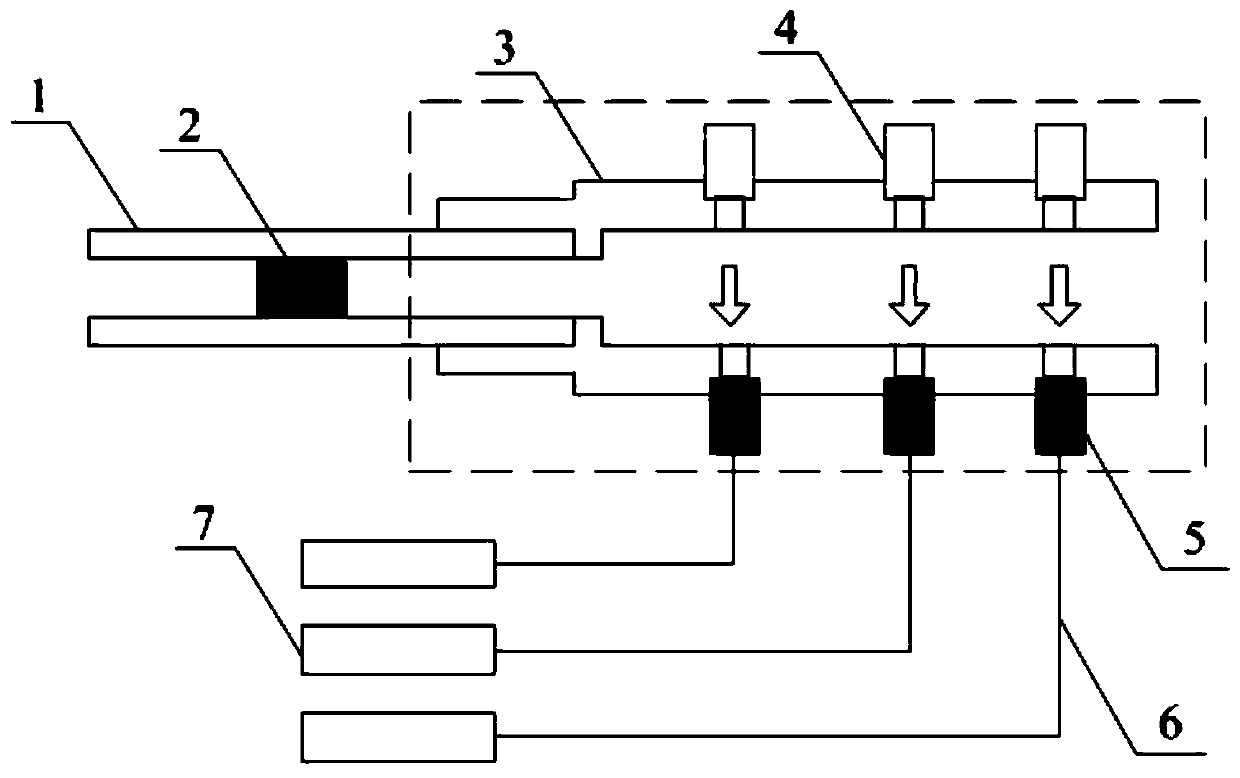
[0042] Such as figure 1 As shown, it is a 10nm particle detection device applied to a ballistic target test provided by Embodiment 1 of the present invention, and the 10nm particle detection device is arranged at the exit of the emitter 1 . The 10nm particle detection device of the present invention includes a fixture 3 , a laser 4 , a coupling lens 5 and a photodetector 7 .

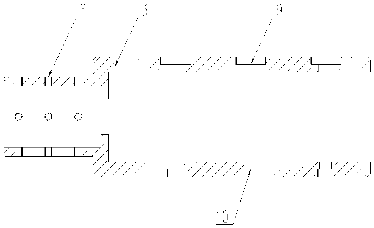
[0043] Among them, the clamp 3 is used to connect the transmitter 1 and provide a mounting base for the components of the device. Specifically, the clamp 3 includes a connection part and a mounting part, referring to figure 2As shown, the left part of the fixture 3 is a connecting part, which has an axial through hole, and the right part of the fixture 3 is a mounting part, which includes a first mounting plate and a second mounting plate, the first mounting plate and the second mounting plate The two mounting plates are arranged in parallel and at intervals to form a light curtain cavity with an open...

Embodiment 2

[0058] Embodiment 2 is basically the same as Embodiment 1, and the similarities will not be described in detail. The difference lies in:

[0059] The device includes a plurality of lasers 4, and the plurality of lasers 4 are arranged at intervals in parallel with the axial direction of the axial through hole. For example, two lasers 4 may be provided for particle velocity measurement, and the corresponding number of coupling lenses 5 and photodetectors 7 is also two. It should be understood that when used for particle velocity measurement, a timer should also be provided according to the test requirements. In the present invention, the numbers of the above-mentioned lasers 4 , coupling lenses 5 and photodetectors 7 can be appropriately increased or decreased. The specific quantity can be set according to the test requirements. When there are multiple lasers 4, coupling lenses 5 and photodetectors 7, the device can realize experiments and researches such as 10nm-level particl...

Embodiment 3

[0061] Embodiment 3 of the present invention provides a 10nm-level particle detection method applied to ballistic target testing, including: providing a light curtain cavity communicated with the outlet channel of the transmitter 1, the light curtain cavity is located in the target chamber, and the two opposite sides of the light curtain cavity The side has an axial opening communicating with the target chamber;

[0062] Provide at least one laser 4, installed on one side of the light curtain cavity;

[0063] Provide the same number of coupling lenses 5 as the number of lasers 4, installed on the other side of the light curtain cavity;

[0064] Provide photodetector 7 with the same number as coupling lens 5, installed outside the target chamber, photodetector 7 is connected with coupling lens 5 through optical fiber 6;

[0065] Debug voltage acquisition equipment;

[0066] Set the parameters of the voltage acquisition device, including acquisition time, sampling rate and tri...


PUM


Abstract

The invention relates to a 10nm-level particle detection device and method applied to a ballistic target test. The device comprises a clamp located in a target chamber, the clamp comprises a connecting part and an installing part, the connecting part is provided with an axial through hole, the installing part comprises a first installing plate and a second installing plate, and the first installing plate and the second installing plate are arranged in parallel at intervals to form a light curtain cavity with an opening; and the device also comprises at least one laser, coupling lenses with thenumber being the same as that of the lenses and photoelectric detectors with the number being the same as that of coupling lenses. According to the scheme, the mode that the clamp is arranged at theoutlet of the emitter is adopted, installation and positioning of the particle detection device are achieved, normal operation of existing equipment is not affected, reliable detection of 10-nm-levelparticles is achieved, and the requirements for speed measurement and control of a 10-nm-level particle collision test can be met.

Description

technical field [0001] The invention relates to the technical field of ultra-high-speed ballistic target testing, in particular to a 10nm particle detection device and method for ballistic target testing. Background technique [0002] The ultra-high-speed ballistic target is an important ground wind tunnel test equipment for the study of hypersonic aerodynamics and ultra-high-speed collision phenomena. The test principle of the ballistic target is: the test gas is static, and the test model flies freely at hypersonic speed in the target chamber to carry out the aerodynamic test. A ballistic target system generally consists of a launcher, a target chamber vacuum system and a velocity measurement control system. [0003] The working process of the ballistic target system is: the launcher launches the particles and the bullet support assembly into the target chamber, and the particles and the bullet support assembly fly freely in the target chamber, and at the same time, the e...

Claims


Application Information

Patent Timeline
IPC IPC(8): G01P5/20G01M9/06
CPCG01M9/065G01P5/20
Inventor 龙耀罗庆罗锦阳邹胜宇陈鸿黄洁姜林李文光
Owner 中国空气动力研究与发展中心超高速空气动力研究所
Why Eureka
Try Eureka