Additive manufacturing device with temperature control function

An additive manufacturing and functional technology, applied in manufacturing auxiliary devices, coating devices, additive processing, etc., can solve problems such as limiting the size of amorphous processing, reduce crack propagation, improve molding quality, and reduce residual stress. Effect

Inactive Publication Date: 2020-08-11
JIANGSU UNIV OF SCI & TECH
View PDF6 Cites 0 Cited by
  • Summary
  • Abstract
  • Description
  • Claims
  • Application Information

AI Technical Summary

Problems solved by technology

[0003] However, for amorphous materials that require a very high cooling rate during the additive process, crystallization is unavoidable, especially in the additive manufacturing process with a l...

Method used


Image

  • Additive manufacturing device with temperature control function
  • Additive manufacturing device with temperature control function
  • Additive manufacturing device with temperature control function

Examples


Embodiment 1

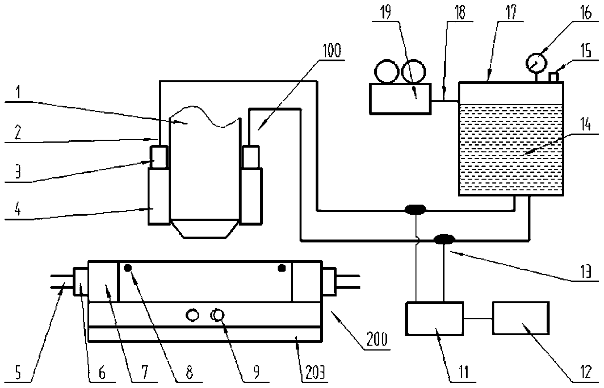
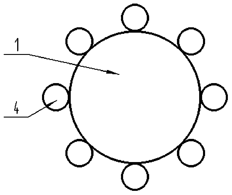
[0020] A kind of additive manufacturing device with temperature control function, such as figure 1 As shown, it includes: a processing head 100 and a working platform 200 . The processing head 100 is composed of a cladding head 1 and a cooling spray gun 4 . A plurality of cooling spray guns 4 are evenly distributed around the cladding head 1 ( figure 2 ), connect the cooling medium input pipeline 2 through the one-way valve 3, and finally connect to the high-pressure tank 17 containing the cooling medium 14. In order to control the flow rate of the cooling medium 14, a speed regulating solenoid valve 13 is installed in the middle of the cooling medium input pipeline 2, which is connected with the programmable controller 11 and the computer 12 in turn. The programmable controller 11 can collect the motion information of the cladding head 1, and set the opening and closing and flow rate of the cooling spray gun 4 in different motion states of the cladding head 1 as required, ...

Embodiment 2

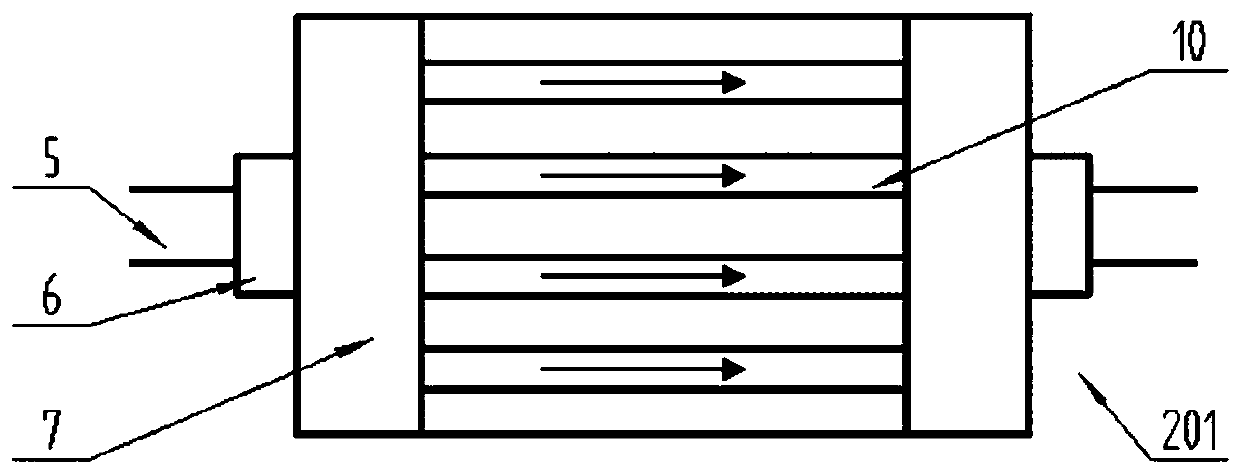
[0025] Use this device to print a piece of iron-based bulk amorphous alloy (BMG, the maximum thickness is greater than 10mm), and the length, width and height are set to 15*10*5mm. Complete the necessary preparatory work, including the installation of the workpiece, the positioning of the processing head and the replacement of the atmosphere. Select liquid nitrogen as the cooling medium to connect the cooling nozzle 4 and the cooling layer 201 respectively, and adjust the flow rate through the temperature information fed back by the thermocouple 8, change the temperature of the cooling layer 201, and set it to 0°C, so that the temperature of the working platform 200 can be cooled evenly. The process of additive accumulation ensures that the printed layer is in a lower temperature range. At the same time, set in the computer 12 to control the cooling nozzle 4 in the forward direction of the cladding head 1 to close, increase in the opposite direction, and decrease on both sides...

Embodiment 3

[0027] Use this device to print a piece of high-entropy alloy (length, width and height: 15*15*10mm). In order to reduce the harm caused by the residual stress, the working platform 200 is heated through the insulating resistance wire 9, the temperature fed back by the thermocouple 8 is set to 400°C, and the preheating is performed for 30 minutes before the additive is started. Stop the heating of the insulating resistance wire 9 after the processing is completed, and take out the workpiece after natural cooling. Before this, the cooling medium in the cooling layer 201 and the cooling spray gun 4 needs to be evacuated.


PUM


Abstract

The invention discloses an additive manufacturing device with a temperature control function. The additive manufacturing device comprises a processing head and a working platform, and is characterizedin that the processing head consists of a cladding head and a plurality of cooling spray guns; the cooling spray guns are mutually independent and used for improving the cooling effect of a machinedarea and improving the cooling rate of a molten pool; and the working platform comprises a cooling layer, a heating layer and a heat insulation layer from top to bottom, the cooling layer is providedwith a thermocouple, and the temperature of the working platform during heating and cooling can be fed back in real time. The cooling and heating functions of the working platform can influence the solidification process of the molten pool, on one hand, the working platform are matched with the cooling spray head, a high cooling rate can be provided for solidification of amorphous materials, on the other hand, residual stress generated in the common metal additive process can be reduced, and therefore the performance of machined parts is improved. The additive manufacturing device is particularly suitable for additive manufacturing of materials which need a high cooling rate or are greatly influenced by residual stress.

Description

technical field [0001] The invention relates to the field of laser processing, in particular to an additive manufacturing device with a temperature control function. Background technique [0002] Additive manufacturing is the process of connecting materials into objects based on 3D model data. This technology has a series of advantages such as high flexibility, no mold, short cycle, and is not limited by part structure and materials. It is widely used in aerospace, automobiles, electronics, etc. , medical, military and other fields, showing a good momentum of development and potential. [0003] However, for amorphous materials that require a very high cooling rate during the additive process, crystallization is unavoidable, especially in the additive manufacturing process with a large laser spot, the cooling rate will gradually decrease with the layer height, resulting in crystallization. The crystallization is more obvious, which severely limits the processing size of amor...

Claims


Application Information

Patent Timeline
IPC IPC(8): B29C64/295B29C64/20B29C64/209B29C64/245B29C64/30B29C64/364B29C64/386B33Y30/00B33Y40/00B33Y50/00
CPCB33Y30/00B33Y40/00B33Y50/00B29C64/20B29C64/209B29C64/245B29C64/295B29C64/30B29C64/364B29C64/386
Inventor 周瑞张胜彪朱伟娜
Owner JIANGSU UNIV OF SCI & TECH
Why Eureka
Try Eureka