
A flue gas cooler applied to mobile medical waste treatment system

A technology of waste treatment system and flue gas cooler, which is applied in the direction of indirect heat exchanger, heat exchanger type, heat exchanger shell, etc., can solve the problem that the medical waste incineration system cannot be applied, the system has high fuel consumption and power consumption, and there is no way Energy and other issues, to achieve the effect of compact structure, reduce system fuel consumption and power consumption, and avoid sudden increase of smoke volume

Active Publication Date: 2022-06-07
HARBIN ELECTRIC POWER GENERATION EQUIP NAT ENG RES CENT CO LTD
View PDF0 Cites 0 Cited by
  • Summary
  • Abstract
  • Description
  • Claims
  • Application Information

AI Technical Summary

Problems solved by technology

At present, cooling water or air is generally used in mobile medical waste treatment systems to directly quench the high-temperature flue gas at the outlet of the incineration chamber at about 1000 °C to about 200 °C, which more than doubles the amount of flue gas passing through the dust removal system and fan system. This has brought about a sudden increase in the amount of flue gas. In order to meet the environmental protection emission requirements, the size of the equipment needs to be larger, and the equipment that is too large is difficult to meet the layout requirements of the mobile medical waste treatment system, so it is necessary to add another car body. To arrange power generation and air compression equipment, resulting in increased investment in equipment
At the same time, in the existing mobile medical waste treatment system, because of the direct quenching, there is no way to recycle the energy, the system fuel consumption and power consumption are relatively high, and the economy of the whole system is poor
[0003] In addition, at present, the air preheater of large thermal power plant boilers or hot water boilers usually has a single-pass arrangement on the flue gas side and a multi-pass arrangement on the air side, and the flue gas temperature does not exceed 400°C. This type of preheater cannot be applied In a medical waste incineration system with a small amount of flue gas and a temperature as high as 1000°C

Method used


Image

  • A flue gas cooler applied to mobile medical waste treatment system
  • A flue gas cooler applied to mobile medical waste treatment system
  • A flue gas cooler applied to mobile medical waste treatment system

Examples


Embodiment 1

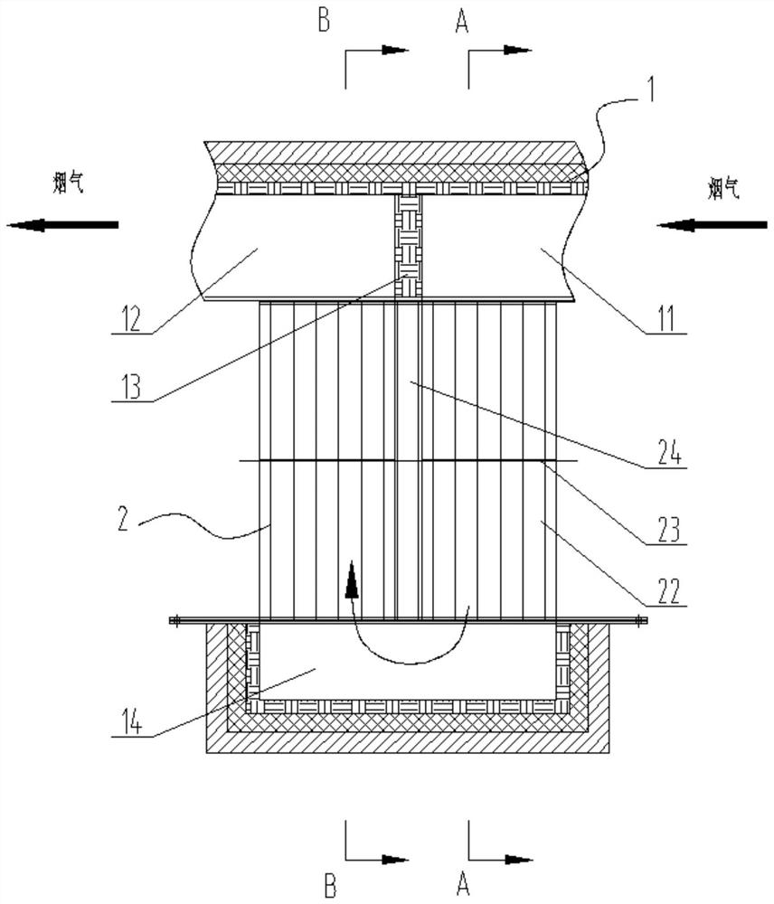
[0022] like figure 1 and Figure 4 As shown, the present invention is a flue gas cooler applied to a mobile medical waste treatment system, including: a flue 1 and a heat exchange tube box 2, the heat exchange tube box 2 is installed in the flue 1, for the convenience of later For maintenance and replacement, the heat exchange tube box 2 and the flue 1 are connected by bolts.

[0023] In order to improve the heat exchange efficiency of the flue gas cooler and improve the structural compactness of the flue gas cooler, the heat exchange tube box 2 is provided with at least two flue gas passages and no less than two single air ventilation chambers , this embodiment takes two flue gas return trips, four air return trips, the flue inlet and flue outlet on the same side, and the heat exchange tube box air inlet and air outlet on the same side as examples. The specific number of return trips can be adjusted according to needs In addition, the layout of the flue inlet and flue outle...

Embodiment 2

[0033] The difference between embodiment 2 and embodiment 1 is that the flue gas in embodiment 1 is changed to flow outside the smoke pipe 22 , while the air is changed to flow inside the smoke pipe 22 .

[0034] work process:

[0035] Flue gas flow

[0036]High-temperature incineration produces high-temperature flue gas of about 1000°C flowing along the flue 1, entering the heat exchange tube box 2 from the flue inlet 11 through the flue pipe 22, and the high-temperature flue gas flows through the flue gas first return, The flue gas is connected to the cavity 14 and the second return of the flue gas. After the flue gas undergoes two return heat exchanges, the temperature of the high-temperature flue gas drops to about 600° C., and finally enters the downstream equipment through the flue outlet 12 .

[0037] air flow

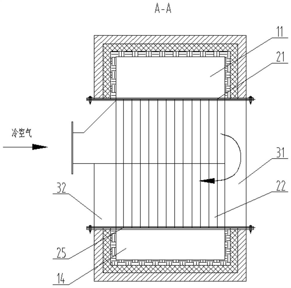
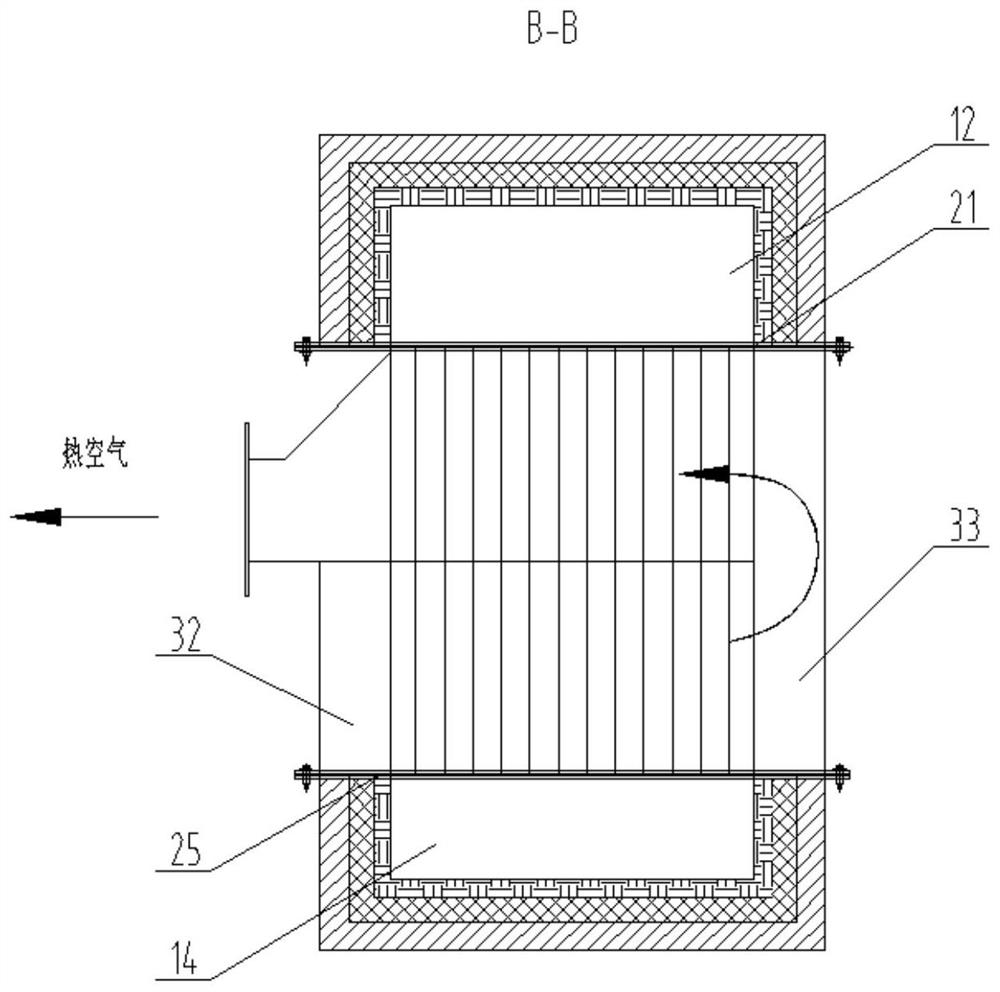
[0038] The cold air is entered by the blower through the air inlet of the heat exchange tube box 2, and the cold air passes through the first air return, the ...


PUM


Abstract

The invention discloses a flue gas cooler applied to a mobile medical waste treatment system, which belongs to the field of energy and environmental protection, and is proposed in view of the large area occupied by the existing equipment and the low heat exchange efficiency, including: a flue and a flue installed in the flue The heat exchange tube box has a flue gas channel and an air heat exchange chamber inside the heat exchange tube box. There are at least two flue gas channels in series in the heat exchange tube box. The flue gas enters the flue gas channel from the flue inlet, and the flue gas After cooling down, it flows back into the flue from the outlet of the flue, and the inlet of the flue and the outlet of the flue are set on the same side or on the opposite side; Single air heat exchange chambers are connected in series to form an air heat exchange chamber. Cold air enters from the air inlet of the heat exchange tube box, exchanges heat with flue gas during the flow process, and the hot air after heat exchange is discharged from the air outlet of the heat exchange tube box. The air inlet and air outlet of the heat exchange tube box are arranged on the same side or different sides. The invention has small volume, compact structure and high heat exchange efficiency.

Description

Technical field: [0001] The invention belongs to the technical field of energy and environmental protection, and in particular relates to a flue gas cooler applied to a mobile medical waste treatment system. Background technique: [0002] Medical waste has the characteristics of space pollution, acute infection and latent pollution. Its viruses and germs are dozens, hundreds or even thousands of times more harmful than ordinary domestic waste. If it is not handled properly, it will cause serious pollution to the environment and may also become the source of epidemics. At present, incineration is mainly used for medical waste disposal, and mobile medical waste disposal equipment can realize on-site incineration and disposal of medical waste, avoiding the risk of virus spread caused by medical waste transfer. At present, cooling water or air is generally used in mobile medical waste treatment systems to directly quench the high-temperature flue gas at the outlet of the incine...

Claims


Application Information

Patent Timeline
Patent Type & Authority Patents(China)
IPC IPC(8): F23J15/06F28D7/16F28F9/02F28F9/10F23G7/00F23G5/08
CPCF23J15/06F28D7/1607F28F9/02F28F9/10F23G7/00F23G5/08Y02E20/30
Inventor 刘宏张春伟王永堂石运鑫谢敏周保东孙正路
Owner HARBIN ELECTRIC POWER GENERATION EQUIP NAT ENG RES CENT CO LTD
Learn More