Broadband patch antenna with stable high gain

A chip antenna, high stability technology, applied in the direction of antenna, resonant antenna, antenna components, etc., can solve the problems of high feed network complexity, limited application, low gain, etc., to achieve stable in-band beam width, low Cross-polarization performance, the effect of expanding the operating bandwidth

Active Publication Date: 2020-08-14
SHENZHEN UNIV
View PDF4 Cites 7 Cited by
  • Summary
  • Abstract
  • Description
  • Claims
  • Application Information

AI Technical Summary

Problems solved by technology

However, the traditional microstrip patch antenna has the following problems: 1. The bandwidth is narrow, which is not suitable for applications in environments with large bandwidth requirements; 2. The gain is low, and the application in the medium and long-distance wireless communication environment is limited. Improving the gain of the antenna by forming an array will lead to higher complexity and lower efficiency of the feed network of the antenna system; 3. Poor cross polarization will seriously affect the anti-interference performance of the antenna
However, the introduction of a feed resonator feed will increase the feed loss of the antenna and increase the complexity of the antenna structure
In addition, the relative bandwidth that these two high-order mode broadband antennas can achieve is only about 6%, which limits their application in wireless communication environments with large bandwidth requirements

Method used


Image

  • Broadband patch antenna with stable high gain
  • Broadband patch antenna with stable high gain
  • Broadband patch antenna with stable high gain

Examples


Embodiment

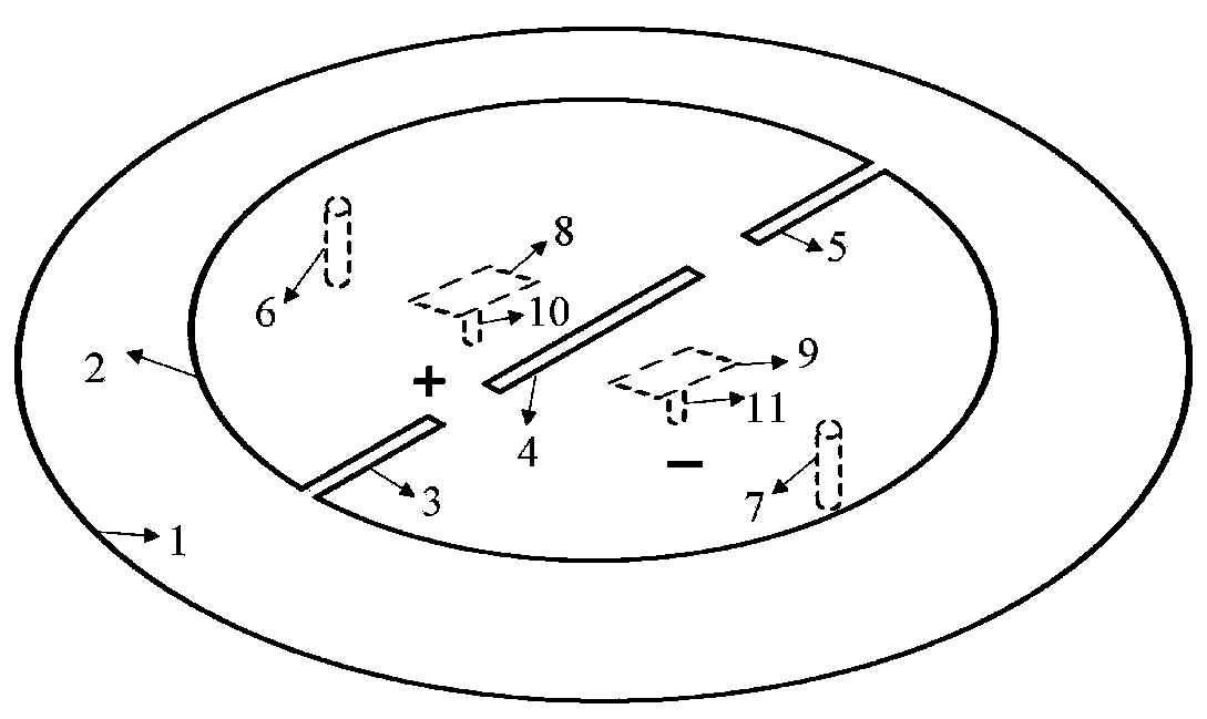
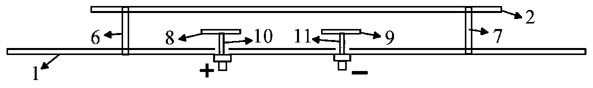
[0031] see figure 1 as well as figure 2 , a broadband patch antenna with stable and high gain, consisting of a metal floor 1, a circular radiation patch 2, a differential feed port, and used to adjust the TM 31 The short-circuit component group of the mode resonance frequency and the coupling metal sheet group used to adjust the coupling strength of the radiation patch; the diameter of the radiation patch 2 is greater than half the free-space wavelength at the central operating frequency, and at its first diameter position settings are used to change the TM 12 The first slot 4 of the surface current distribution of the mode antenna is used to change the TM 31 The second slit 3 and the third slit 5 of the surface current distribution of the model antenna; the second slit 3 and the third slit 5 are separated on both sides of the first slit 4; the coupling metal sheet group is located between the metal floor 1 and the Between the radiation patches 2; the coupling metal sheet ...


PUM


Abstract

The invention provides a broadband patch antenna with a stable high gain. The broadband patch antenna is composed of a metal floor, a circular radiation patch, a differential feed port, a first shortcircuit assembly, a second short circuit assembly, a first metal sheet and a second metal sheet. The diameter of the radiation patch is greater than the half free space wavelength at the central working frequency, and a first gap, a second gap and a third gap are arranged at the first diameter position of the radiation patch, and the second gap and the third gap are respectively arranged at two sides of the first gap; the first metal sheet and the second metal sheet are positioned between the metal floor and the radiation patch; the differential feed port is provided with a first feed body used for feeding to the first metal sheet and a second feed body used for feeding to the second metal sheet; the metal floor is connected with the radiation patch through the first short-circuit assemblyand the second short-circuit assembly; and the first metal sheet and the second metal sheet, the first feed body and the second feed body, and the first short circuit assembly and the second short circuit assembly are respectively distributed in a mirror image manner about a plane which passes through the first diameter and is vertical to the radiation patch.

Description

technical field [0001] The invention relates to the technical field of patch antennas, in particular to a broadband patch antenna with stable and high gain. Background technique [0002] With the rapid development of wireless communication, microstrip patch antennas are widely used in various wireless communication devices due to their advantages of low profile, light weight and low cost. However, the traditional microstrip patch antenna has the following problems: 1. The bandwidth is narrow, which is not suitable for applications in environments with large bandwidth requirements; 2. The gain is low, and the application in the medium and long-distance wireless communication environment is limited. Improving the gain of the antenna by forming an array will increase the complexity of the feeding network of the antenna system and reduce the efficiency; 3. The cross polarization is poor, which seriously affects the anti-interference performance of the antenna. [0003] In recen...

Claims


Application Information

Patent Timeline
Patent Type & Authority Applications(China)
IPC IPC(8): H01Q9/04H01Q1/36H01Q1/00H01Q1/24H01Q1/48
CPCH01Q9/0414H01Q9/045H01Q1/36H01Q1/002H01Q1/241H01Q1/48
Inventor 洪凯东张晓袁涛
Owner SHENZHEN UNIV
Why Eureka
Try Eureka