Medium-temperature SCR denitration system and denitration method for kiln tail flue gas

A denitrification and flue gas technology, applied in separation methods, chemical instruments and methods, gas treatment, etc., can solve the problems of fine dust particles in cement kiln flue gas, clogging of SCR catalyst bed, and limited efficiency of cyclone dust collectors. Improve denitration efficiency and operating life, remove NOx efficiently at low cost, reduce poisoning and deactivation

Inactive Publication Date: 2020-08-18
INST OF PROCESS ENG CHINESE ACAD OF SCI
View PDF7 Cites 2 Cited by
  • Summary
  • Abstract
  • Description
  • Claims
  • Application Information

AI Technical Summary

Problems solved by technology

In this process, a cyclone dust collector is arranged in front of the SCR reactor, which can reduce the dust entering the SCR reactor, but the dust particles of the cement kiln flue gas are small, and the efficiency of the cyclone dust collector is limited
[0005] CN109985522 discloses an SCR flue gas denitrification reactor embedded in a waste heat boiler for denitrification of cement kiln flue gas and a method thereof. By adding a vertical expansion section of the waste heat boiler, several layers of catalyst layers are set in the expansion section to avoid separate The SCR denitrification reactor is set up to reduce the pressure drop of the system. However, due to the extremely high dust concentration of the flue gas entering the waste heat boiler, the original ash hopper at the bottom of the waste heat boiler needs to pass through the SCR reactor. Layers are also very easy to cause blockage, and the expansion of the waste heat boiler is also limited by the actual boiler layout margin, which is difficult to achieve in the actual process

Method used


Image

  • Medium-temperature SCR denitration system and denitration method for kiln tail flue gas

Examples


Embodiment 1

[0090] This embodiment provides a medium-temperature SCR denitrification method for kiln tail flue gas. SCR denitrification is performed on the kiln tail gas discharged from a 3000t / d new dry process cement kiln. The denitrification method specifically includes the following steps:

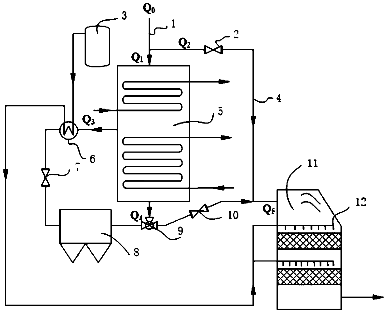
[0091] (1) Kiln tail gas Q discharged from cement kiln 0 The volume flow rate is 368240Nm 3 / h, kiln tail flue gas Q 0 Medium dust concentration is 50g / Nm 3 , the temperature is 280°C, NO x The concentration is 200mg / Nm 3 , in the kiln tail flue gas Q 0 Before entering the waste heat recovery device 5, the kiln tail flue gas Q 0 Divided into the first kiln tail flue gas Q 1 and the second kiln tail gas Q 2 , the first kiln tail flue gas Q 1 The volume flow rate of kiln tail flue gas Q 0 10% of the total volume flow, that is, the first kiln tail flue gas Q 1 The volume flow rate is 36824g / Nm 3 , the second kiln tail flue gas Q 2 The volume flow rate is 331416g / Nm 3 ;

[0092] The firs...

Embodiment 2

[0097] This embodiment provides a medium-temperature SCR denitrification method for kiln tail flue gas. SCR denitrification is performed on the kiln tail gas discharged from a 3200t / d new dry process cement kiln. The denitrification method specifically includes the following steps:

[0098] (1) Kiln tail gas Q discharged from cement kiln 0 The volume flow rate is 436320Nm 3 / h, kiln tail flue gas Q 0 Medium dust concentration is 60g / Nm 3 , the temperature is 290°C, NO x The concentration is 223mg / Nm 3 , in the kiln tail flue gas Q 0 Before entering the waste heat recovery device 5, the kiln tail flue gas Q 0 Divided into the first kiln tail flue gas Q 1 and the second kiln tail gas Q 2 , the first kiln tail flue gas Q 1 The volume flow rate of kiln tail flue gas Q 0 40% of the total volume flow, that is, the first kiln tail flue gas Q 1 The volume flow rate is 174528g / Nm 3 , the second kiln tail flue gas Q 2 The volume flow rate is 261792g / Nm 3 ;

[0099] The fir...

Embodiment 3

[0104] This embodiment provides a medium-temperature SCR denitrification method for kiln tail flue gas. SCR denitrification is performed on the kiln tail gas discharged from a 3500t / d new dry process cement kiln. The denitrification method specifically includes the following steps:

[0105] (1) Kiln tail gas Q discharged from cement kiln 0 The volume flow rate is 528530Nm 3 / h, kiln tail flue gas Q 0 Medium dust concentration is 70g / Nm 3 , the temperature is 300℃, NO x The concentration is 300mg / Nm 3 , in the kiln tail flue gas Q 0 Before entering the waste heat recovery device 5, the kiln tail flue gas Q 0 Divided into the first kiln tail flue gas Q 1 and the second kiln tail gas Q 2 , the first kiln tail flue gas Q 1 The volume flow rate of kiln tail flue gas Q 0 50% of the total volume flow, that is, the first kiln tail flue gas Q 1 The volume flow rate is 264265g / Nm 3 , the second kiln tail flue gas Q 2 The volume flow rate is 264265g / Nm 3 ;

[0106] The firs...


PUM

PropertyMeasurementUnit
Radianaaaaaaaaaa
Specific surface areaaaaaaaaaaa
Apertureaaaaaaaaaa

Abstract

The invention provides a medium-temperature SCR denitration system and denitration method for kiln tail flue gas. The denitration system comprises a waste heat recovery device, a heat exchange deviceand an SCR denitration device, wherein a high-temperature flue gas outlet of the waste heat recovery device is connected with the heat exchange device, and an outlet of the heat exchange device and amedium-temperature flue gas outlet of the waste heat recovery device are combined into one path and then connected into the SCR denitration device. The medium-temperature SCR denitration system provided by the invention can meet the increasingly strict NOx emission standard of the kiln tail flue gas of a cement kiln and provide technical support for ultralow emission of NOx at the kiln tail of thecement kiln. Through flue gas back-mixing, on one hand, the temperature of the flue gas at the outlet of the waste heat recovery device can be increased, and on the other hand, the content of smoke dust entering the SCR denitration device is reduced, so that the SCR denitration efficiency is improved, and meanwhile, system dust accumulation and catalyst poisoning are reduced.

Description

technical field [0001] The invention belongs to the technical field of waste gas treatment, and relates to an industrial flue gas denitrification system and method, in particular to a medium-temperature SCR denitrification system and a denitrification method for kiln tail flue gas. Background technique [0002] At present, selective non-catalytic reduction (SNCR) technology is widely used for denitrification of cement kiln flue gas in my country. x The removal efficiency is generally about 60%, which can basically meet the existing emission standards. However, the SNCR denitrification technology has problems such as low denitrification efficiency and serious ammonia escape, and it is difficult to meet the further stringent ultra-low emission standards. Selective catalytic reduction (SCR) denitrification technology has mild reaction conditions and high denitrification efficiency (90%). It has been widely used in the thermal power industry, but its application in the cement in...

Claims


Application Information

Patent Timeline
IPC IPC(8): F27D17/00B01D53/86B01D53/90B01D53/56B01D50/00
CPCB01D50/00B01D53/8631B01D53/90B01D2251/206B01D2251/2062B01D2251/2067B01D2255/2065B01D2255/20723B01D2255/2073B01D2255/20738B01D2255/20776B01D2255/2092B01D2258/0283F27D17/004F27D17/008F27D2017/006Y02P10/25
Inventor 朱廷钰郭旸旸罗雷
Owner INST OF PROCESS ENG CHINESE ACAD OF SCI
Why Eureka
Try Eureka