A vacuum continuous casting casting production equipment

A technology of continuous casting and production equipment, which is applied in the direction of casting equipment, metal processing equipment, casting melt containers, etc., which can solve the problems of discontinuous production process, shrinkage cavity, long production preparation time, etc., and achieve reasonable device structure design, Reduced oxidation and volatilization, less consumption of consumable parts

Active Publication Date: 2021-06-22
陕西斯瑞扶风先进铜合金有限公司
View PDF7 Cites 0 Cited by
  • Summary
  • Abstract
  • Description
  • Claims
  • Application Information

AI Technical Summary

Problems solved by technology

[0003] In the prior art, vacuum smelting + semi-continuous casting of ingots or non-vacuum continuous casting is often used for smelting and casting of alloy materials such as copper alloys and aluminum alloys; however, the above two methods of smelting and casting alloys generally exist: 1. Non-ferrous metals such as copper and aluminum are easy to oxidize, absorb gas, volatilize and absorb impurities during smelting and casting, resulting in defect segregation, shrinkage cavity, shrinkage porosity, inclusions and other defects; 2. The surface roughness of the ingot is poor, and subsequent processing The amount of milling chips increases; 3. The solidification structure of the dummy head and the ingot tail of the ingot produced by semi-continuous casting is uneven, and the head and tail of a single ingot need to be sawed off, and the actual material utilization rate is about 90%; 4. Semi-continuous casting The continuous ingot production process is discontinuous, the production preparation time is too long, and the production efficiency is low

Method used


Image

  • A vacuum continuous casting casting production equipment
  • A vacuum continuous casting casting production equipment
  • A vacuum continuous casting casting production equipment

Examples


Embodiment

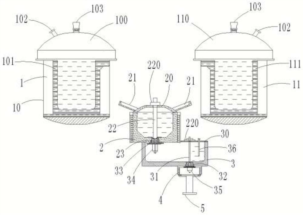
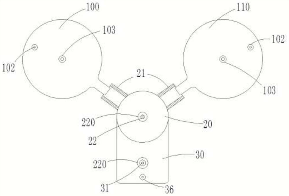
[0034] Example: such as figure 1The shown a kind of vacuum continuous casting casting production equipment comprises vacuum degassing furnace 1, intermediate furnace 2, alloy furnace 3, crystallizer 4 and continuous casting machine 5, and vacuum degassing furnace 1 comprises the first vacuum degassing furnace 10 and The second vacuum degassing furnace 11, the first vacuum degassing furnace 10 and the second vacuum degassing furnace 11 have the same structure, and are arranged on the same horizontal plane, the first vacuum degassing furnace 10 and the second vacuum degassing furnace 11 upper ends respectively A first furnace cover 100 and a second furnace cover 110 are provided, and a first crucible 101 and a second crucible 111 are respectively arranged inside, and observation ports 102 and temperature measurement and sampling are respectively provided on the first furnace cover 100 and the second furnace cover 110 port 103; the joints of the first crucible 101 and the second ...


PUM


Abstract

The invention discloses a vacuum continuous casting production equipment, which comprises a vacuum degassing furnace, an intermediate furnace, an alloy furnace, a crystallizer and a continuous casting machine. There are two vacuum degassing furnaces, each of which is equipped with a vacuum degassing furnace. There is a furnace cover and a crucible. The intermediate furnace is equipped with an intermediate furnace sealing cover, a chute and a first stopper rod. The intermediate furnace is provided with a first base. The first stopper rod is pressed against the concave hole on the first base. There is an alloy furnace sealing cover and a second stopper rod, a second base is provided inside the alloy furnace, the bottom end of the second stopper rod is pressed against the concave hole on the second base, a sliding nozzle is arranged inside the alloy furnace, and a sliding nozzle is provided at the lower end of the alloy furnace. There is a first drainage tube, a second drainage tube is set at the lower end of the second base, the crystallizer is set at the lower end of the alloy furnace, a temperature measuring system is movably inserted on the sealing cover of the alloy furnace, the continuous casting machine is fixedly installed at the lower end of the crystallizer, and the continuous casting machine The pulling head penetrates the bottom of the crystallizer; the structure design of the invention is reasonable, the loss of alloy material is small, and it is suitable for mass promotion.

Description

technical field [0001] The invention relates to the technical field of continuous casting equipment, in particular to a vacuum continuous casting production equipment. Background technique [0002] The continuous casting process is that after the molten steel produced by the converter is refined in the refining furnace, the molten steel needs to be cast into billets of different types and specifications. The continuous casting section is the production process of continuously casting the refined molten steel into billets. The main equipment includes a rotary table, a tundish, a crystallizer, and a tension leveler. [0003] In the prior art, vacuum smelting + semi-continuous casting of ingots or non-vacuum continuous casting is often used for smelting and casting of alloy materials such as copper alloys and aluminum alloys; however, the above two methods of smelting and casting alloys generally exist: 1. Non-ferrous metals such as copper and aluminum are easy to oxidize, abs...

Claims


Application Information

Patent Timeline
Patent Type & Authority Patents(China)
IPC IPC(8): B22D11/14B22D11/041B22D11/113B22D41/18B22D41/20B22D41/50C22C9/00
CPCB22D11/004B22D11/041B22D11/113B22D11/141B22D41/18B22D41/20B22D41/50C22C9/00
Inventor 孙君鹏刘琦高斌梁相博张青队梁建斌王文斌
Owner 陕西斯瑞扶风先进铜合金有限公司
Why Eureka
Try Eureka