

Coated cutting tool
A cutting tool and coating technology, used in the manufacture of tools, workpieces, drill accessories, etc., can solve problems such as shortening tool life, and achieve the effect of excellent machined surface quality and long tool life.
Active Publication Date: 2020-08-25
TUNGALOY CORP
View PDF6 Cites 0 Cited by
- Summary
- Abstract
- Description
- Claims
- Application Information
AI Technical Summary
Problems solved by technology
This leads to the problem of shortened tool life
Method used
View moreImage
Smart ImageViewing Examples

Examples
Embodiment
[0138] Hereinafter, the present invention will be described in more detail with examples, but the present invention is not limited to these examples.
[0139] [Substrate]
[0140] For the following substrates, after rounding the ridge line of the cutter head with a SiC brush, the surface of the substrate was cleaned and used.
[0141] [Substrate 1]
[0142] Shape: CNMG120412
[0143] Material: Cemented carbide (84.4WC-10.8Co-1.9TiC-0.2TiN-2.4NbC-0.3ZrC (above mass%))
[0144] [Substrate 2]
[0145] Shape: CNMG120412
[0146] Material: Hard alloy (93.5WC-6.1Co-0.4Cr 3 C 2 (The above is mass %))
Login to View More PUM
| Property | Measurement | Unit |
|---|---|---|
| thickness | aaaaa | aaaaa |
| thickness | aaaaa | aaaaa |
| thickness | aaaaa | aaaaa |
Abstract
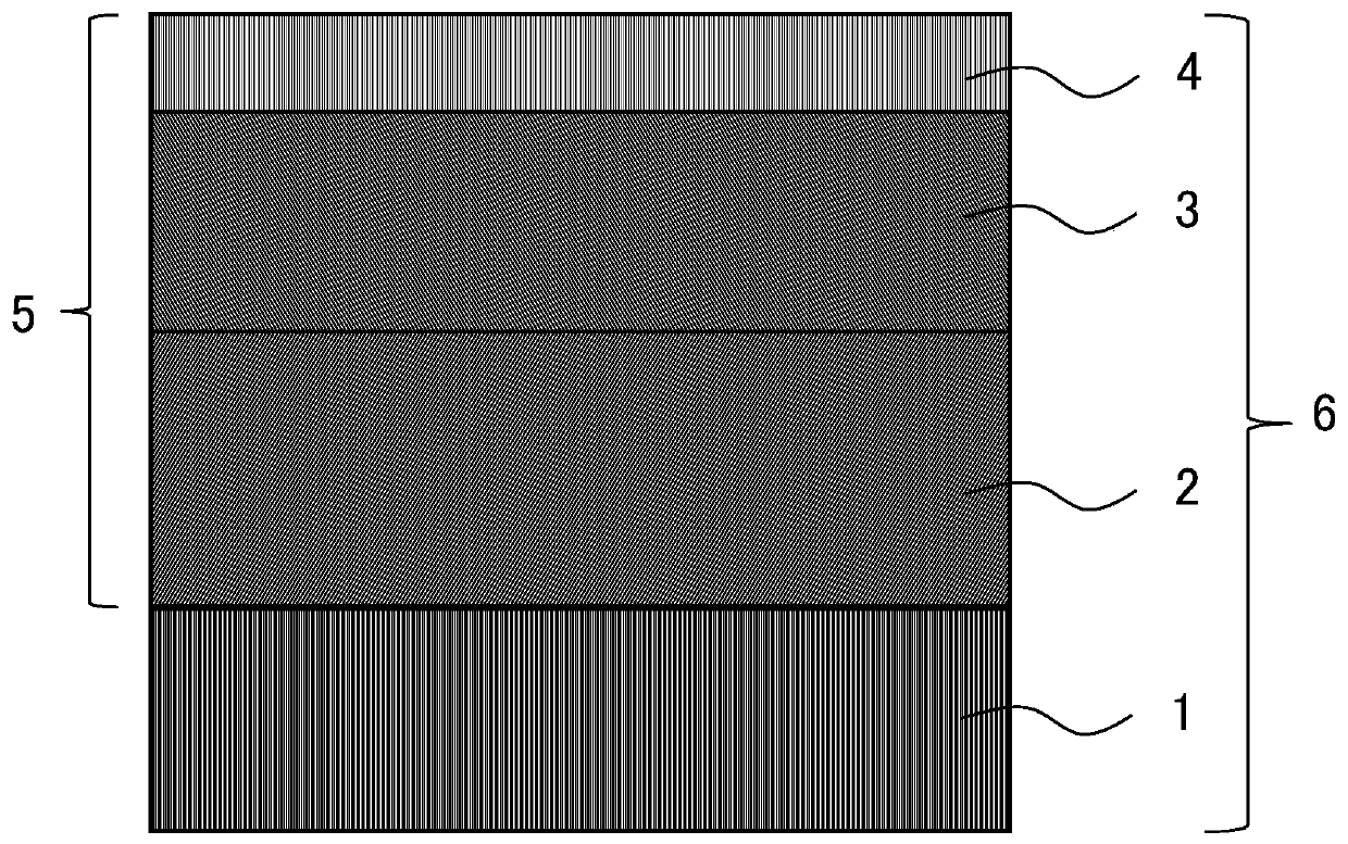
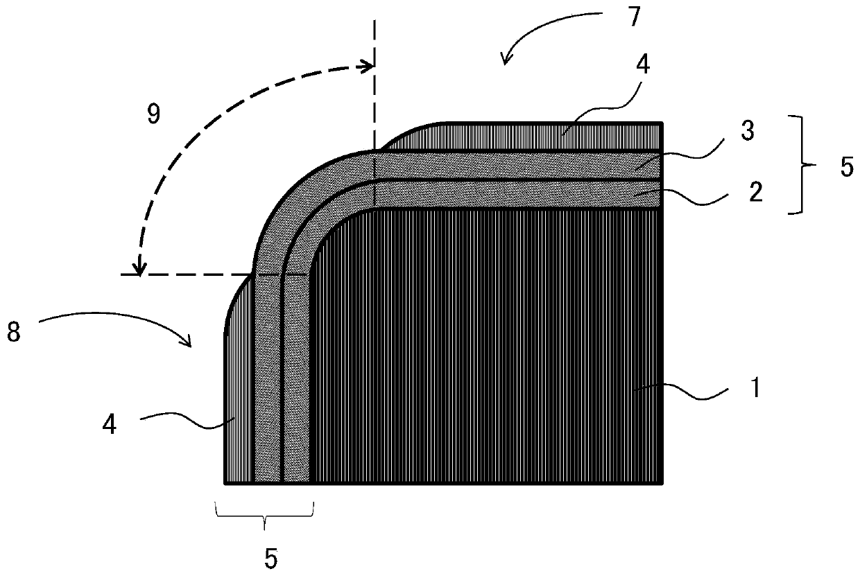
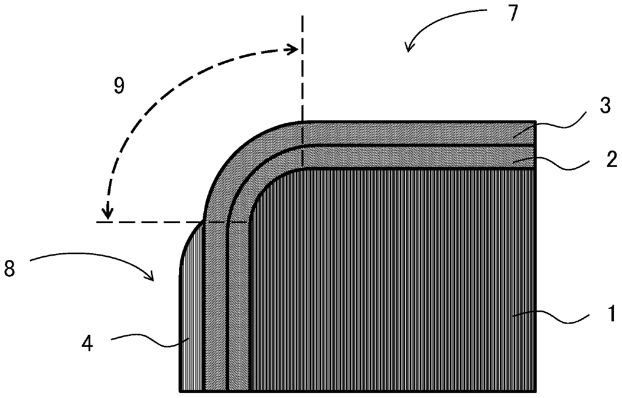
Provided is a coated cutting tool of long tool life and that affords superior machined surface quality. The coated cutting tool includes a substrate and a coating layer. The coated cutting tool includes at least one flank face, at least one rake face, and a honing part rounded and connecting the flank face and the rake face. The coating layer includes a lower layer, an intermediate layer and an upper layer, in this order from the side of the substrate. The lower layer is composed of more than one Ti compound layer made up of a specific Ti compound. The intermediate layer contains alpha-type Al2O3. The upper layer contains a specific compound, an average thickness of the coating layer on the flank face side is more than 5.0 um and less than 30.0 um. A first cross-section that is located ata distance of 1 [mu] m from the interface on the upper layer side of the intermediate layer toward the substrate side and that is parallel to the interface between the substrate and the lower layer, and a second cross-section that is located at a distance of 1 [mu] m from the interface on the intermediate layer side of the upper layer toward the interface on the opposite side thereof and that is parallel to the interface between the base material and the lower layer respectively satisfy the specified requirements. The intermediate layer is exposed at least in the honed part.
Description
Technical field [0001] The invention relates to a coated cutting tool. Background technique [0002] Conventionally, coated cutting tools made by vapor-depositing a coating layer with a total film thickness of 3-20 μm on the surface of a substrate made of cemented carbide by chemical vapor deposition have been used for cutting steel, cast iron, and the like. As the coating layer, it is known that, for example, a titanium compound, aluminum oxide (Al 2 O 3 ), etc., or two or more kinds of multilayer coating layers. [0003] Patent Document 1 describes a surface-coated cutting tool characterized in that a lower layer composed of a titanium compound layer and an aluminum oxide layer are deposited on the surface of a tool base composed of tungsten carbide-based cemented carbide. (Al 2 O 3 Layer) as a hard coating layer, which consists of aluminum oxide layer (Al 2 O 3 The (006) plane orientation coefficient TC(006) of the upper layer composed of layer) is 1.8 or more, and the ratio of...
Claims
Login to View More Application Information
Patent Timeline
 Patent Type & AuthorityApplications(China)
IPC IPC(8): B23B27/00B23B27/14B23C5/16B23B51/00C23C16/32C23C16/34C23C16/36C23C16/30C23C16/38C23C16/40
CPCB23B27/00B23B27/14B23C5/16B23B51/00C23C16/32C23C16/34C23C16/36C23C16/30C23C16/38C23C16/403B23B2228/10B23B2228/105B23C2228/10C23C14/0641C23C14/0664C23C14/0635C23C30/005C23C28/04C23C28/044B23B27/148C23C16/308C23C16/405
Inventor城地司高桥欣也福岛直幸
OwnerTUNGALOY CORP