Electronic water pump magnetic transmission device for automobile

A technology of electronic water pump and magnetic drive, which is applied to pump devices, electromechanical devices, components of pumping devices for elastic fluids, etc. It can solve the problems of impossibility of immersion, increased rotation noise, and large frictional resistance inside the bearing, etc., to achieve Improve working stability, reduce frictional resistance, and improve bearing life

Pending Publication Date: 2020-08-25
KUNSHAN LONGZHONG MAXGREEN AUTO PARTS
View PDF0 Cites 1 Cited by
  • Summary
  • Abstract
  • Description
  • Claims
  • Application Information

AI Technical Summary

Problems solved by technology

[0004] 1) The bearings assembled between the inner magnetic ring sleeve and the support shaft are all metal sliding bearings, with round surface contact, large frictional resistance inside the bearing, and short life;
[0005] 2) Metal sliding bearings have poor insulation properties and cannot be immersed in the circulating cooling fluid of hydrogen energy batteries that require strict insulation, and conductive ions will be precipitated;
[0006] 3) There is a gap between the inner ring of the sliding bearing and the surface of the support shaft, which cannot be tightly fitted, resulting in high rotational noise;
[0007] 4) The sliding bearing has axial clearance, which will be damaged by friction
[0008] Especially when the existing electronic water pump for automobiles encounters continuous dry running, the rotation stability will deteriorate, and the rotation noise will increase. After a long time, it will easily cause the failure of the water pump to stall and slow down.

Method used


Image

  • Electronic water pump magnetic transmission device for automobile
  • Electronic water pump magnetic transmission device for automobile

Examples


Embodiment

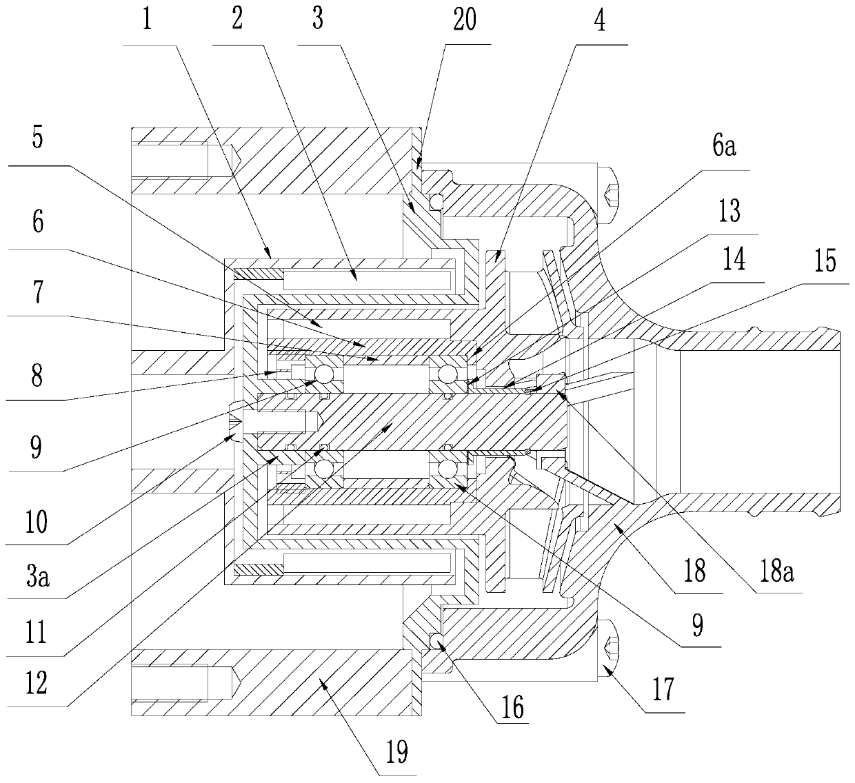
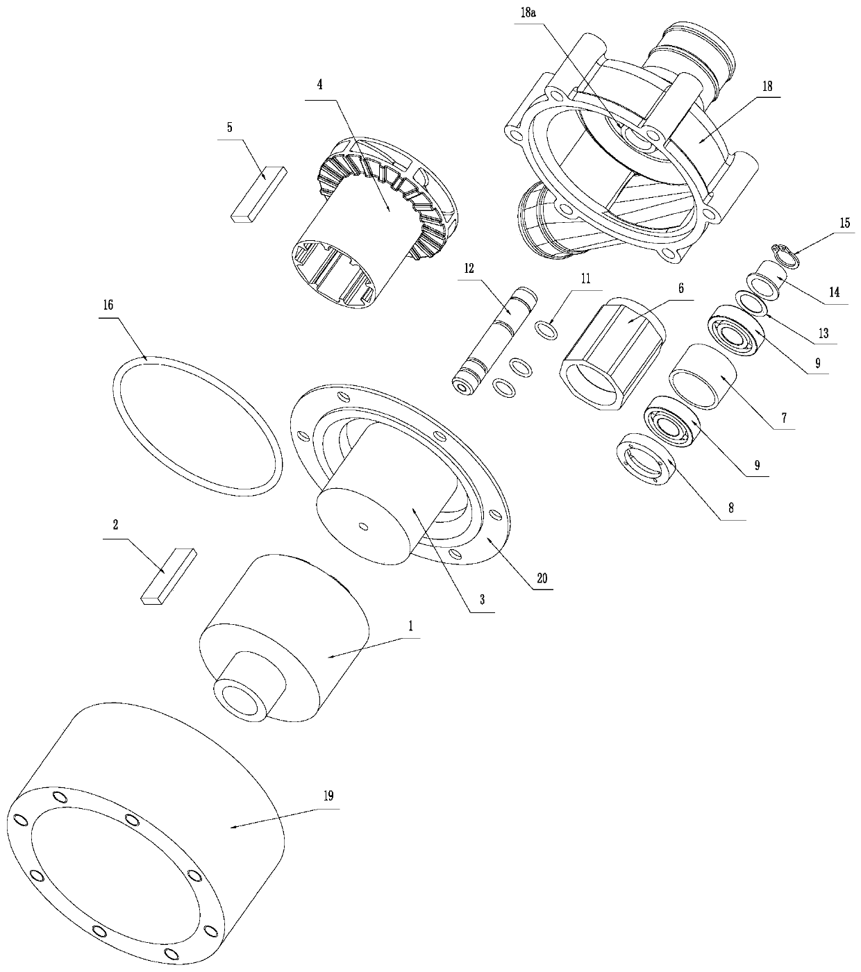
[0028] Embodiment: combine below figure 1 and figure 2 The specific implementation of the electronic water pump magnetic drive device for automobiles provided by the present invention is described as follows:

[0029] First of all, it has the pump head shell 18, the connection shell 19 and the non-metallic spacer 3 as in the conventional technology. The pump head shell 18 is located at the front end, and the connection shell 19 is located at the rear. There is a connecting ring 20 extending between the pump head shell 18 and the connecting shell 19, and the connecting ring 20 on the pump head shell 18, the connecting shell 19 and the non-metallic spacer 3 is provided with a total of 6 positioning holes corresponding to one week ( figure 2 not marked). During actual assembly, the connecting ring 20 and the pump head casing 18 are locked and fixed to the connecting casing 19 together by passing through six connecting casing connecting screws 17 . and if figure 1 As shown, ...


PUM


Abstract

The invention discloses an electronic water pump magnetic transmission device for an automobile. The electronic water pump magnetic transmission device comprises a pump head shell and a connecting shell fixed to the rear end of the pump head shell. An inner magnetic ring sleeve and an outer magnetic ring sleeve isolated through a nonmetallic isolating sleeve are arranged in the connecting shell, an outer permanent magnet is attached to the inner circumference of the outer magnetic ring sleeve, and an inner permanent magnet is attached to the periphery of the inner magnetic ring sleeve. The inner magnetic ring sleeve and an impeller arranged in the pump head shell are fixed. A supporting shaft fixed to the nonmetallic isolating sleeve is further included. The electronic water pump magnetictransmission device is characterized in that the inner magnetic ring sleeve is assembled on the supporting shaft through multiple axially distributed ceramic ball bearings, the adjacent ceramic ball bearings abut against each other through gaskets, the outer side of the ceramic ball bearing at the frontmost end abuts against a circle of inner flange formed on the inner magnetic ring sleeve, and the outer side of the ceramic ball bearing at the tail end abuts against an externa thread nut mounted in the inner magnetic ring sleeve. Embedding grooves are formed in the positions, corresponding tothe ceramic ball bearings, of the supporting shaft, and O-shaped rings are embedded. The O-shaped rings are in flexible close fit with the inner rings of the corresponding ceramic ball bearings. The device is low in rotating noise, long in service life and more stable and reliable in operation.

Description

technical field [0001] The invention relates to an electronic water pump magnetic drive device for automobiles. Background technique [0002] Electronic water pumps for automobiles are the key equipment for water circulation, cooling or on-board water supply systems on special vehicles such as new energy vehicles and RVs. The known electronic water pump for automobiles is mainly composed of two parts, a DC brushless motor and a magnetic transmission device. The core structure of the magnetic transmission device is an inner magnetic ring sleeve and an outer magnetic ring sleeve. The outer permanent magnet is attached to the week. The inner magnetic ring sleeve is arranged inside the outer magnetic ring sleeve, and an inner permanent magnet is attached to the outer periphery of the inner magnetic ring sleeve. And the inner and outer magnetic ring sleeves are designed to be separated by a non-metallic spacer sleeve fixed between the connection sleeve and the pump head shell. ...

Claims


Application Information

Patent Timeline
Patent Type & Authority Applications(China)
IPC IPC(8): F04D13/02F04D29/044F01P5/12F16C33/78F16C25/08F16C37/00F16J15/3268H02K5/173H02K49/10B60P3/36
CPCB60P3/36F01P5/12F04D13/026F04D29/044F16C25/08F16C33/7806F16C37/007F16C2206/40F16C2360/00F16J15/3268H02K5/1732H02K49/102H02K49/106
Inventor 黄政爱杨海波丁玉璋
Owner KUNSHAN LONGZHONG MAXGREEN AUTO PARTS
Why Eureka
Try Eureka