Microstructure channel and lubricating oil groove composite guide rail and method
A lubricating oil groove and micro-texture technology, which is used in metal processing equipment, maintenance and safety accessories, metal processing machinery parts, etc., can solve problems such as the contradiction between groove size requirements and requirements, and achieve increased oil storage capacity and improved lubrication effect. , Improve the effect of uniform distribution
- Summary
- Abstract
- Description
- Claims
- Application Information
AI Technical Summary
Problems solved by technology
Method used
Image
Examples
Embodiment 1
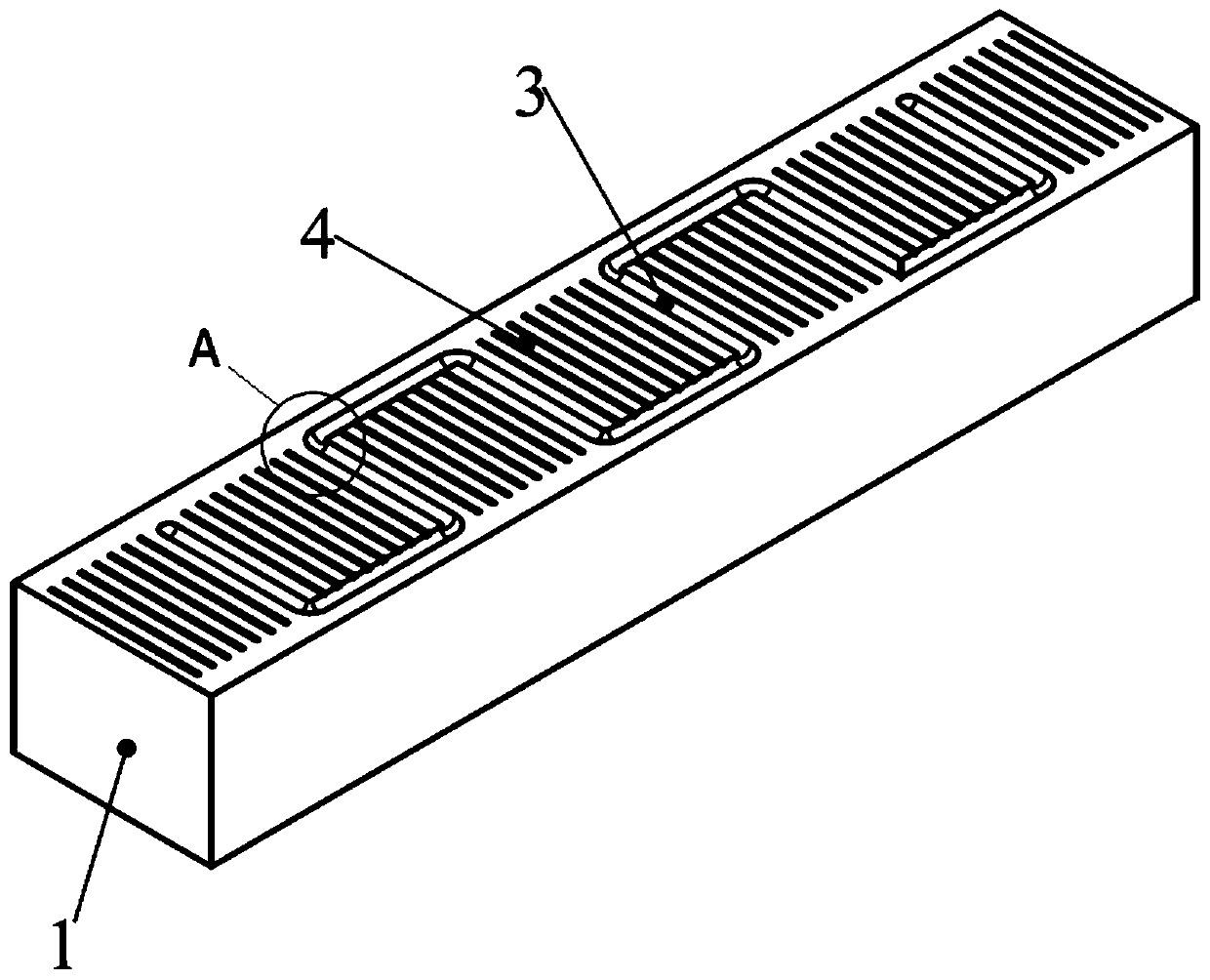
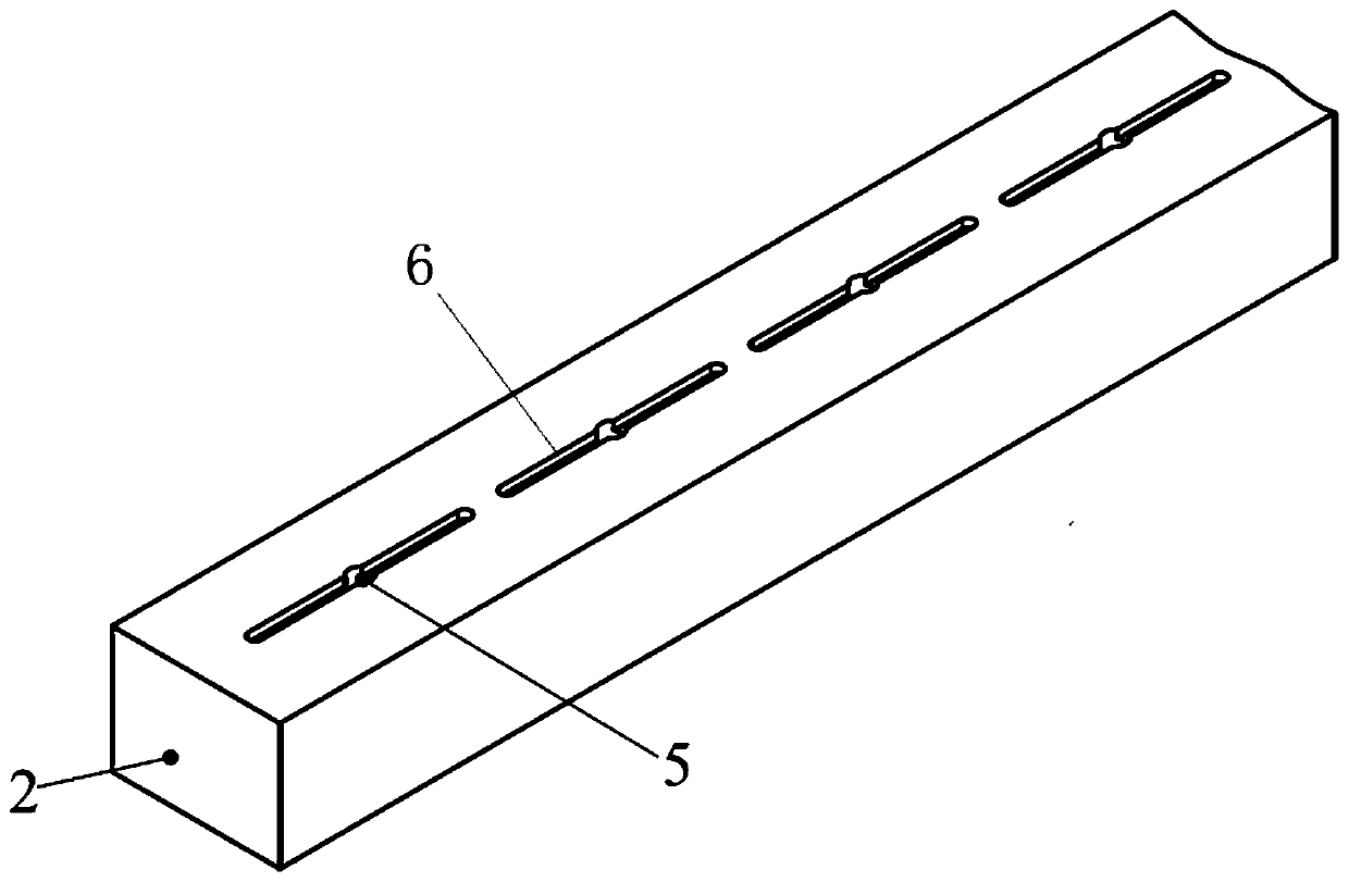
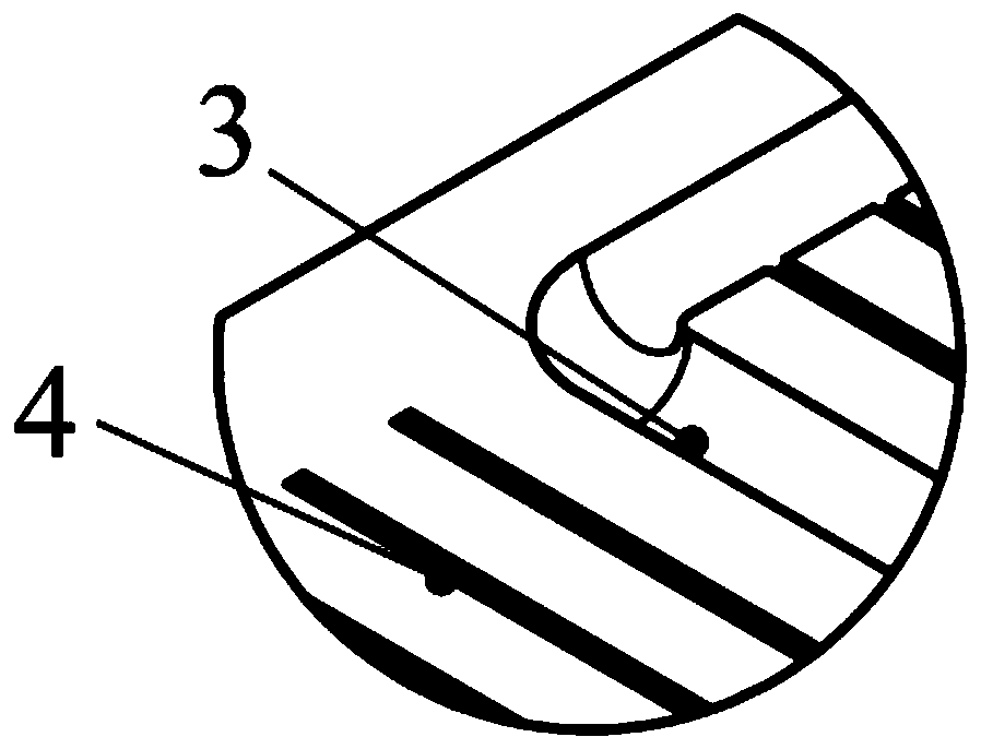
[0040] Such as Figure 1-3 As shown, on the guide rail surface of the moving parts (that is, the surface in contact with the fixed guide rail 2 in the sliding guide rail 1), a lubricating oil groove 3 and a micro-textured groove 4 are provided. The depth is 1.5 mm, and the width is 3 mm; the micro-textured groove 4 has a rectangular cross section, the depth is 200 μm, the width is 500 μm, and the distance between adjacent micro-textured grooves 4 is 1000 μm; 2, on the surface in contact with the sliding guide rail 1), an oil inlet hole 5 and a straight oil inlet groove 6 are offered. The lubricating oil flows in from the oil inlet, passes through the oil inlet groove 6, enters the lubricating oil groove 3 and the micro-textured groove 4, and forms an oil film during sliding, which avoids dry friction and improves the lubricating effect.
Embodiment 2
[0042] Such as figure 2 ,4 , 5, on the guide rail surface of the moving parts (that is, the surface in contact with the fixed guide rail 2 in the sliding guide rail 1), a lubricating oil groove 3 and a micro-texture structure are provided. The lubricating oil groove 3 is a linear oil groove with a rectangular section, and the depth is 1mm. The width is 3 mm; the micro-texture is a rectangular cross-section, the depth is 30 μm, the width is 50 μm, and the spacing is 500 μm; on the guide rail surface of the fixed part (that is, the surface in contact with the sliding guide rail 1 in the fixed guide rail 2), an oil inlet hole 5 is provided With straight oil inlet groove6. The lubricating oil flows in from the oil inlet, passes through the oil inlet groove 6, enters the lubricating oil groove 3 and the micro-textured groove 4, and forms an oil film during sliding, which avoids dry friction and improves the lubricating effect.
Embodiment 3
[0044] This embodiment provides a dimensional design method for a composite guide rail with micro-textured grooves and lubricating oil grooves, which includes the following steps:
[0045] Step 1. Select the appropriate lubricating oil tank form according to the layout of the guide rail and the oil supply method.
[0046] Step 2, designing micro-textured grooves perpendicular to the sliding direction in the oil groove gap.
[0047] Step 3: When the lubricating oil viscosity is low, the sliding speed is high, and the oil supply is easy, the micro-textured groove with small width and large spacing should be used; when the lubricating oil viscosity is high, the sliding speed is low, and the oil supply is difficult, the large width and small groove should be used. pitch micro-textured grooves.
PUM
 Abstract
Description
Claims
Application Information
 - R&D
- Intellectual Property
- Life Sciences
- Materials
- Tech Scout
- Unparalleled Data Quality
- Higher Quality Content
- 60% Fewer Hallucinations
Browse by: Latest US Patents, China's latest patents, Technical Efficacy Thesaurus, Application Domain, Technology Topic, Popular Technical Reports.
© 2025 PatSnap. All rights reserved.Legal|Privacy policy|Modern Slavery Act Transparency Statement|Sitemap|About US| Contact US: help@patsnap.com


