A rubber pad line cutting machine
A cutting machine and rubber pad technology, applied in metal processing and other directions, can solve the problems of increasing labor force, fast tool wear and high labor intensity, and achieve the effect of saving cost, improving output and quality, and saving labor.
- Summary
- Abstract
- Description
- Claims
- Application Information
AI Technical Summary
Problems solved by technology
Method used
Image

Examples
Embodiment 1
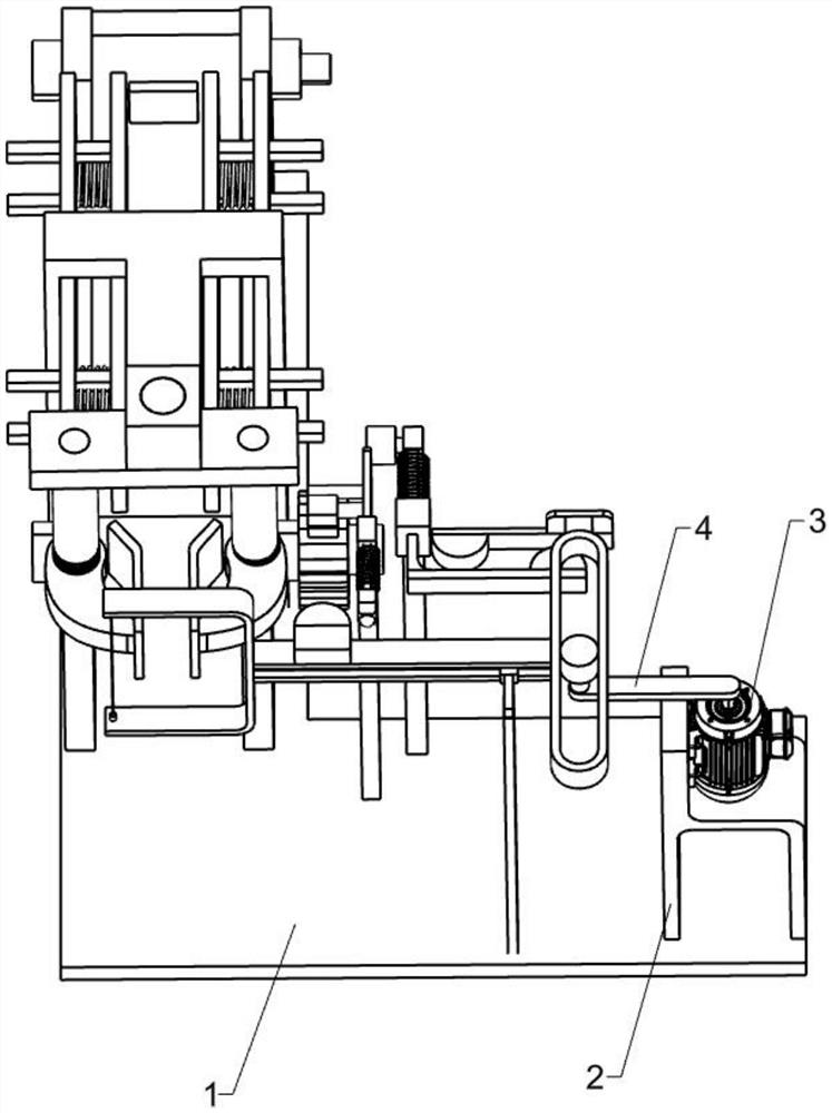
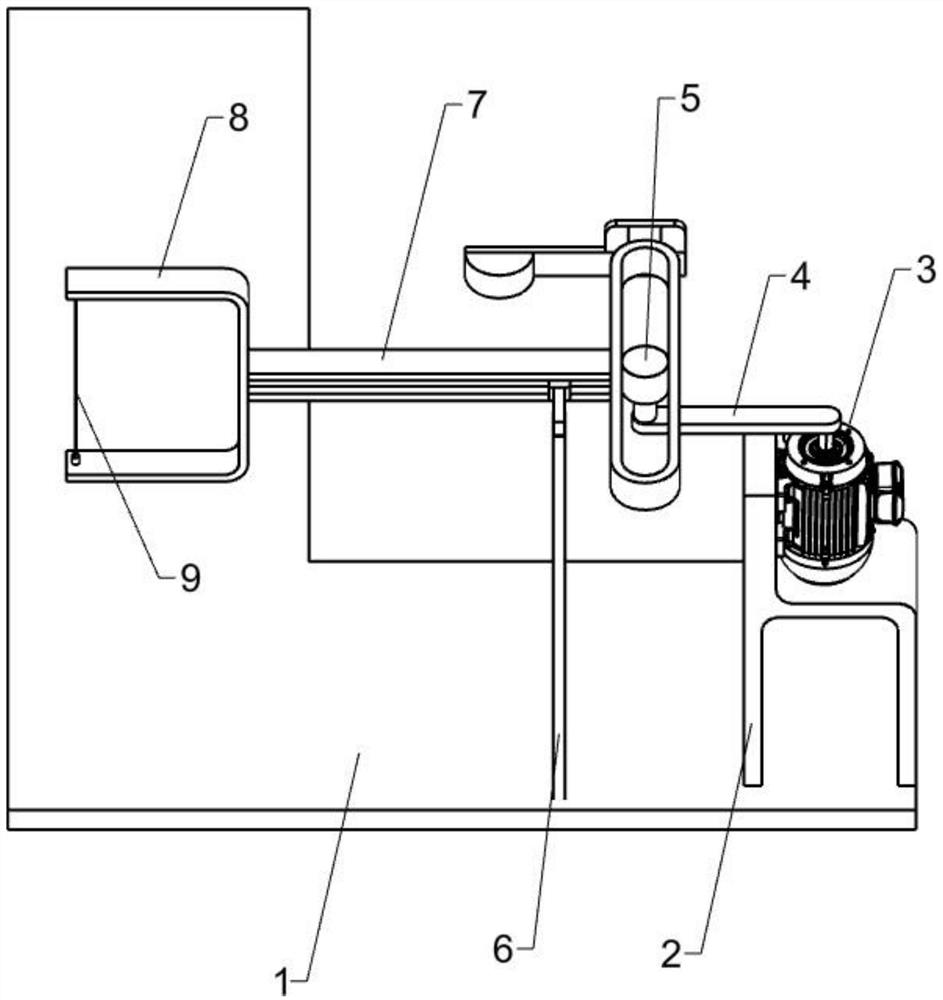
[0068] A rubber pad line cutting machine, such as Figure 1-3 As shown, it includes a bottom plate 1, a support seat 2, a motor 3, a swing rod 4, a swing wheel 5, a pole 6, a T-shaped guide rail 7, a U-shaped frame 8, an electric cutting line 9 and a transmission device. The bottom plate 1 is L type, the support base 2 is fixed on the right part of the bottom plate 1, the motor 3 is installed on the support base 2, the swing rod 4 is fixed on the output shaft of the motor 3, the swing wheel 5 is connected to the right end of the swing rod 4 in rotation, and the pole-6 Fixed on the bottom plate 1, located on the left side of the support seat 2, the T-shaped guide rail 7 is slidably connected to the pole 1 6 through the slider, the swing wheel 5 is movably connected with the T-shaped guide rail 7, and the U-shaped frame 8 is fixed on the T-shaped guide rail 7 At the left end, the electric cutting line 9 is installed on the U-shaped frame 8, and the transmission device is fixed o...
Embodiment 2
[0073] On the basis of embodiment 1, a kind of rubber pad line cutting machine, such as Figure 4 As shown, a clamping device is also included. The clamping device includes a clamping bracket 16, a straight rod 17, a torsion spring 18, a clamping grip 19 and a splint 20. The clamping bracket 16 is fixed on the bottom plate 1 and is located on the front side of the transmission device. , there are two straight rods 17, which are respectively fixed symmetrically under the clamping bracket 16, two clamps 19, which are respectively rotatably connected to the lower part of the straight rod 17, and two torsion springs 18 are respectively sleeved on the straight rod 17, One end is connected with the straight rod 17, and the other end is connected with the gripper 19. There are two splints 20, which are fixedly connected to the gripper 19 respectively.
[0074] When the rubber pad passes through the splint 20, the splint 20 moves to both sides through the gripper 19. At the same time,...
Embodiment 3
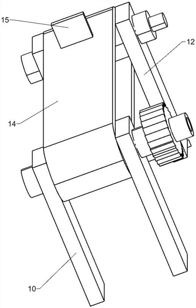
[0076] On the basis of embodiment 2, a kind of rubber pad line cutting machine, such as Figure 5-6 Shown, also comprise propelling device one, and propelling device one comprises support plate 21, square rod 22, flat plate 23, stage clip 24, ratchet 25, sliding support one 27, straight slide bar 28, mounting plate 31, ratchet 32 There are two limit rods 33 and two support plates 21, which are respectively symmetrically fixed to the clamping bracket 16 and located on the rear side of the clamping bracket 16. There are four square rods 22, which are respectively symmetrically slidably connected to the support plate 21. The flat plate 23 is Two, symmetrically fixed to the square rod 22, located above the conveyor belt 14, respectively located on both sides of the push block 15, four compression springs 24, one end connected to the support plate 21, the other end connected to the flat plate 23, the ratchet 25 is fixed On the right side of the output shaft of the transmission whee...
PUM
 Abstract
Description
Claims
Application Information
 - R&D
- Intellectual Property
- Life Sciences
- Materials
- Tech Scout
- Unparalleled Data Quality
- Higher Quality Content
- 60% Fewer Hallucinations
Browse by: Latest US Patents, China's latest patents, Technical Efficacy Thesaurus, Application Domain, Technology Topic, Popular Technical Reports.
© 2025 PatSnap. All rights reserved.Legal|Privacy policy|Modern Slavery Act Transparency Statement|Sitemap|About US| Contact US: help@patsnap.com