Femtosecond fiber laser and working method thereof

A femtosecond fiber and laser technology, applied in the field of medical devices, can solve the problems of fiber core mode field matching, power amplification stage laser spontaneous oscillation, and limiting fiber output power, which are not easy to inject signals, so as to ensure the simplicity of the structure and the circuit. Safety, suppression of nonlinear effects, cost reduction effects

Pending Publication Date: 2020-08-28
JIHUA LAB
View PDF0 Cites 1 Cited by
  • Summary
  • Abstract
  • Description
  • Claims
  • Application Information

AI Technical Summary

Problems solved by technology

If the operation is wrong, the control system is wrong or the temperature is too high, it will cause strong laser self-oscillation in the power amplifier stage, burn out the gain fiber, or even burn out all the optical components
Secondly, pumping semiconductor lasers are used separately in the seed laser light source and the power amplification stage, and different driving circuits and complex control circuits are used, resulting in increased costs
Thirdly, due to the use of a pump / signal fiber combiner between the seed light source and the power amplifier stage, it is not easy to achieve the core mode field matching between the injected signal fiber and the output fiber, which limits the output power of the fiber

Method used


Image

  • Femtosecond fiber laser and working method thereof

Examples


Embodiment 1

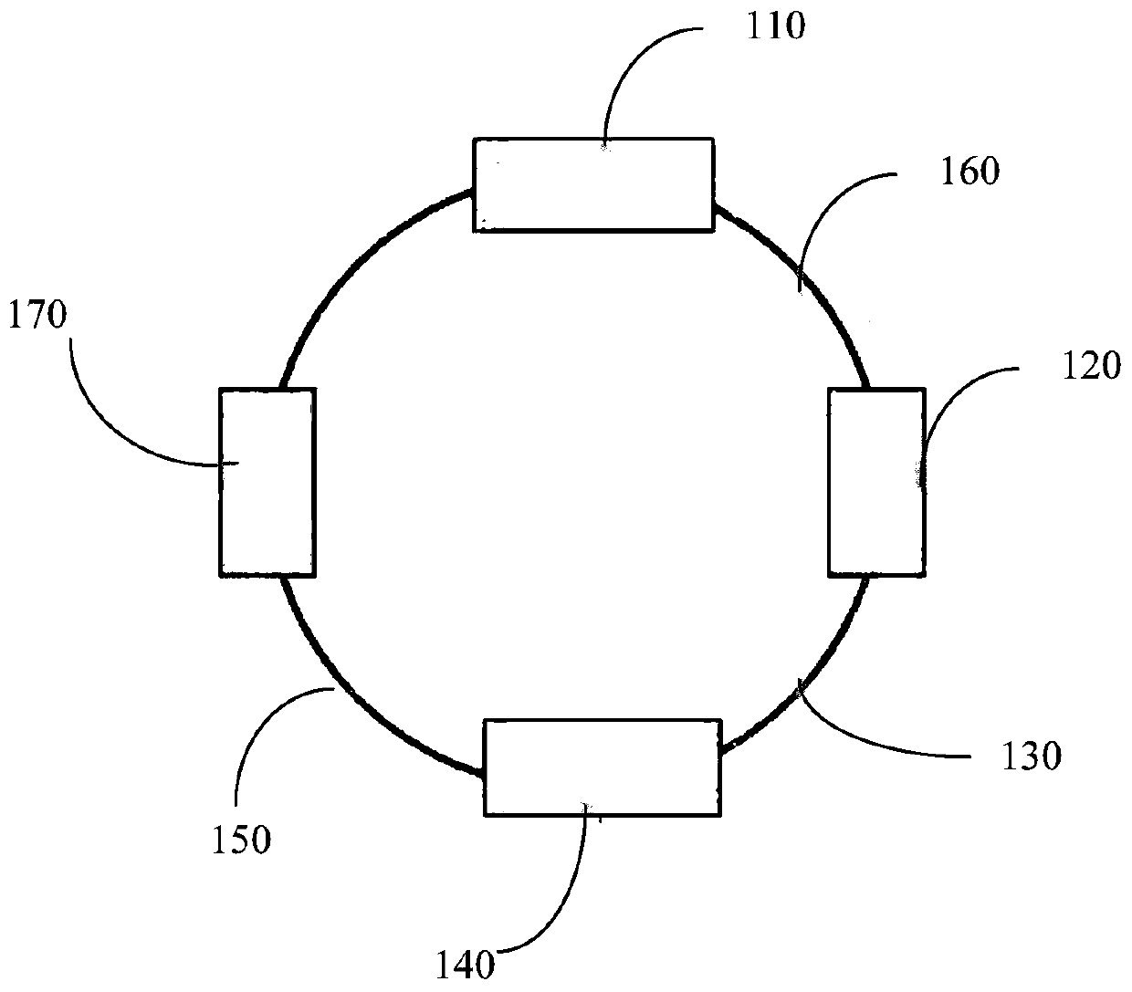
[0029] see figure 1 , is a schematic structural diagram of a femtosecond fiber laser provided by the present invention, including: a self-mode-locked fiber oscillator 110, a pump module 120, a first active fiber 130, a first Bragg grating 140, and a second active fiber 150 , a polarization maintaining fiber 160 and an amplifier 170, the cladding of the second active fiber 150 is engraved with a second Bragg grating.

[0030] Specifically, the polarization maintaining fiber 160 is placed between the self-mode-locked fiber oscillator 110 and the pump module 120, and the first active fiber 130 is placed between the first Bragg grating 140 and the Between the second active optical fiber 150, the self-mode-locked optical fiber oscillator 110, the polarization maintaining optical fiber 160, the pump module 120, the first active optical fiber 130, the first Bragg grating 150, the second active optical fiber 160 and the amplifier 170 are sequentially Seamless fusion forms an all-fibe...

Embodiment 2

[0048] The present invention also provides a working method of a femtosecond fiber laser described in Embodiment 1, comprising the steps of:

[0049] Step S110: the self-mode-locked fiber oscillator 110 generates and outputs the first femtosecond pulsed laser beam;

[0050] Step S120: the first femtosecond pulsed laser beam enters the pump module 120 through the polarization maintaining fiber 160 to form pump light;

[0051] Step S130: the pump light enters the first active optical fiber 130 and oscillates in the resonator formed by the first Bragg grating 140 and the second Bragg grating to form a second femtosecond pulsed laser beam;

[0052] Step S140: the second femtosecond pulsed laser beam is transmitted to the amplifier 170 through the second Bragg grating for power amplification to form a third femtosecond pulsed laser beam;

[0053] Step S150: The third femtosecond pulsed laser beam is output to the self-mode-locked fiber oscillator 110, and the self-mode-locked fibe...


PUM

PropertyMeasurementUnit
diameteraaaaaaaaaa
diameteraaaaaaaaaa
wavelengthaaaaaaaaaa

Abstract

The invention provides a femtosecond fiber laser. The optical fiber laser comprises a self-mode-locking optical fiber oscillator, a pumping module, a first active optical fiber, a first Bragg grating,a second active optical fiber, a polarization maintaining optical fiber and an amplifier, the femtosecond optical fiber laser provided by the invention has a special cavity structure, does not need optical path mechanical adjustment, can realize femtosecond optical fiber laser output with high average power and stable output, and ensures the structural simplicity and circuit safety of the deviceat the same time. The number of used optical parts can be reduced, the use of passive optical fibers is reduced, the nonlinear effect is inhibited, and the cost is reduced.

Description

technical field [0001] The invention relates to the technical field of medical devices, in particular to a femtosecond fiber laser and a working method thereof. Background technique [0002] In recent years, with the advancement of fiber laser technology, the system based on ultrashort pulse fiber laser has been widely used in many application research fields due to its compact structure, high conversion efficiency and long-term stable operation. The application research of femtosecond laser is the most typical. Fiber laser has rapidly emerged in the development of laser technology due to its high efficiency, easy integration, and excellent beam quality, and has become a hot research topic in academia and industry. The multi-field application and potential development of femtosecond fiber laser technology also puts forward higher requirements on the output performance of the laser, which needs to have both high laser power and high reliability. [0003] At present, in orde...

Claims


Application Information

Patent Timeline
Patent Type & Authority Applications(China)
IPC IPC(8): H01S3/067H01S3/08H01S3/0933H01S3/10H01S3/11
CPCH01S3/06716H01S3/0675H01S3/06791H01S3/08018H01S3/0933H01S3/10007H01S3/1109
Inventor 周辉
Owner JIHUA LAB
Why Eureka
Try Eureka