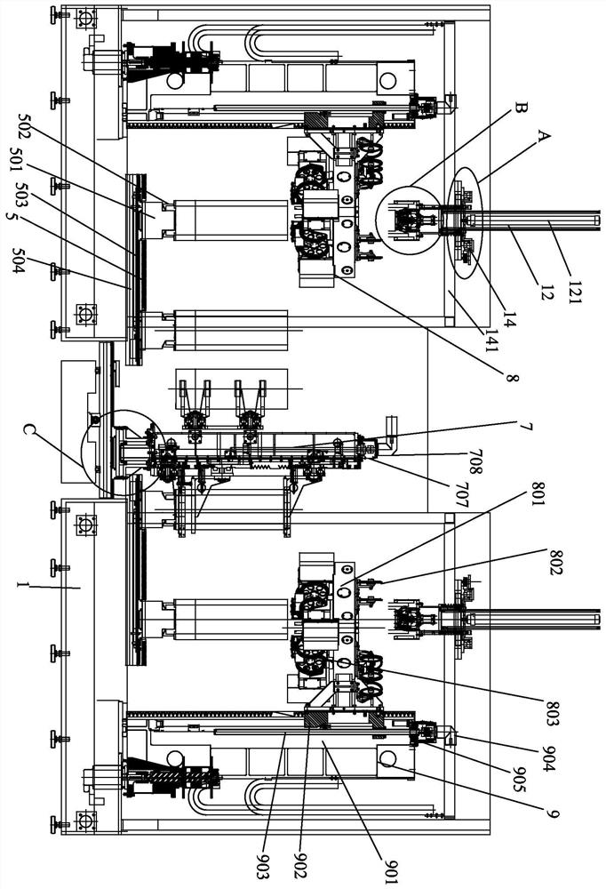
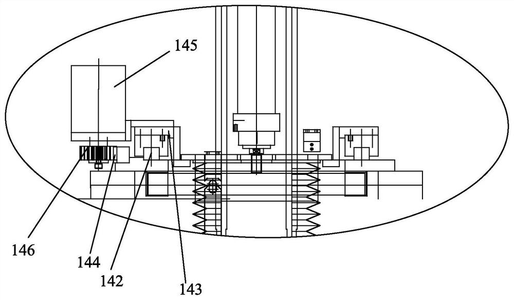
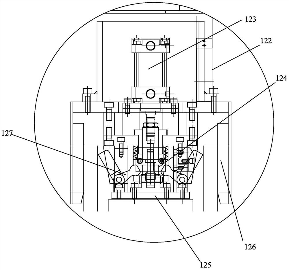
Double-silicon-rod diamond wire squaring machine

A technology of diamond wire and square cutting machine, which is applied in the direction of working accessories, fine working devices, stone processing equipment, etc., can solve the problems of wire mesh not working, high diamond wire breakage rate, high cost, etc., and achieve easy maintenance , Grab and transport stability, increase work efficiency

Pending Publication Date: 2020-09-04
DALIAN LIANCHENG NUMERICAL CONTROL MACHINE
View PDF0 Cites 5 Cited by
  • Summary
  • Abstract
  • Description
  • Claims
  • Application Information

AI Technical Summary

Problems solved by technology

[0002] Most of the existing silicon rod squarers are horizontal single-piece squarers, the cooling water is not easy to flow into the cutting position, resulting in insufficient cutting accuracy, and the diamond wire cutting has a high rate of wire breakage, because the traditional cutting wire network is parallel or vertical On the axis of the machine tool, the cutting wheel or cutting roller near the side of the lifting column is not easy to maintain
And the edge grabbing of the traditional square cutting machine is not stable
However, the existing double-rod square cutting machines only put two single-rod square cutting machines together, and each single-machine square cutting machine is equipped with a crystal wire detection device, a silicon rod grabbing manipulator system and other devices, resulting in Low internal utilization and high cost
And the existing vertical double-rod square cutting machine adopts a cutting head to cut two silicon rods simultaneously, and a set of take-up and release device, so once a wire net is disconnected, another wire net cannot work.

Method used


Image

  • Double-silicon-rod diamond wire squaring machine
  • Double-silicon-rod diamond wire squaring machine
  • Double-silicon-rod diamond wire squaring machine

Examples


Embodiment Construction

[0061] It should be noted that, in the case of no conflict, the embodiments of the present invention and the features in the embodiments can be combined with each other. The present invention will be described in detail below with reference to the accompanying drawings and examples.

[0062] In order to make the purpose, technical solutions and advantages of the embodiments of the present invention clearer, the technical solutions in the embodiments of the present invention will be clearly and completely described below in conjunction with the drawings in the embodiments of the present invention. Obviously, the described embodiments It is only some embodiments of the present invention, but not all embodiments. The following description of at least one exemplary embodiment is merely illustrative in nature and in no way taken as limiting the invention, its application or uses. Based on the embodiments of the present invention, all other embodiments obtained by persons of ordina...


PUM


Abstract

The invention provides a double-silicon-rod diamond wire squaring machine comprising a lathe bed extending in the left-right direction. Single-silicon-rod cutting systems are symmetrically arranged onthe left side and the right side of the lathe bed. A feed system and a discharge system are arranged on the front side of the middle portion of the lathe bed. A crystal line detection system used fordetecting silicon rod crystal lines is arranged on the rear side of the middle portion of the lathe bed. A cross slide table system is arranged on the middle portion of the lathe bed and comprises alower slide table system extending in the front-back direction and an upper slide table system extending in the left-right direction. A silicon rod grabbing mechanical hand system used for grabbing silicon rods is installed on the upper slide table system. Two squaring machines share one crystal line detection device and one silicon rod grabbing mechanical hand system, and meanwhile cutting nets of the two squaring machines do not influence each other.

Description

technical field [0001] The invention relates to the technical field of silicon rod processing, in particular to a double silicon rod diamond wire squarer. Background technique [0002] Most of the existing silicon rod squarers are horizontal single-piece squarers, the cooling water is not easy to flow into the cutting position, resulting in insufficient cutting accuracy, and the diamond wire cutting has a high rate of wire breakage, because the traditional cutting wire network is parallel or vertical On the axis of the machine tool, the cutting wheel or cutting roller close to the side of the lifting column is not easy to maintain. Moreover, the edge grabbing of the traditional square cutting machine is not stable. However, the existing double-rod square cutting machines only put two single-rod square cutting machines together, and each single-machine square cutting machine is equipped with a crystal wire detection device, a silicon rod grabbing manipulator system and other...

Claims


Application Information

Patent Timeline
Patent Type & Authority Applications(China)
IPC IPC(8): B28D5/04B28D7/04B28D7/00
CPCB28D5/0058B28D5/0082B28D5/045
Inventor 金明来周江辉聂凤军许博刘丽娟
Owner DALIAN LIANCHENG NUMERICAL CONTROL MACHINE
Why Eureka
Try Eureka