Microstrip film isolator test fixture

A technology of microstrip film and test fixture, which is applied in the direction of instruments, measuring electronics, and measuring devices, can solve the problems of not meeting the requirements of reliability screening and testing of components, low economic efficiency, and low testing efficiency, and achieve improvement The effect of test efficiency and test accuracy, high test accuracy, and wide frequency range of test coverage

Pending Publication Date: 2020-09-04
CASIC DEFENSE TECH RES & TEST CENT
View PDF7 Cites 1 Cited by
  • Summary
  • Abstract
  • Description
  • Claims
  • Application Information

AI Technical Summary

Problems solved by technology

Although this test method has high precision, the test efficiency is low. At the same time, soldering will cause unnecessary damage to the device, which does not meet the requirements of reliability screening and testing of components, especially for large-scale device testing. not tall

Method used


Image

  • Microstrip film isolator test fixture
  • Microstrip film isolator test fixture
  • Microstrip film isolator test fixture

Examples


Embodiment 2

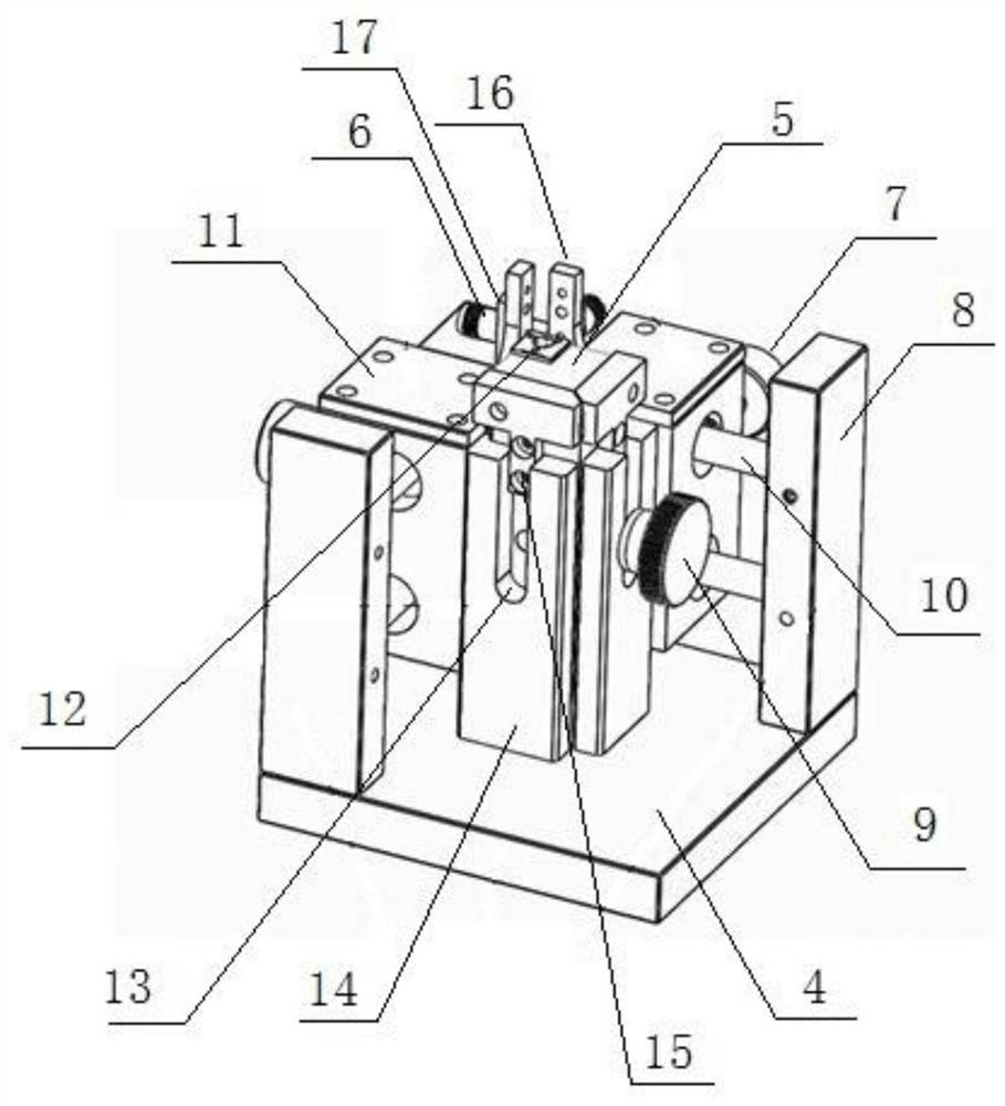
[0024] Embodiment 2, a kind of microstrip film isolator test fixture described in embodiment 1, described elastic support mechanism comprises support frame 14 and compression spring, and compression spring is located at the bottom of stage 5 and is fixed on test platform 4 The support frame 14 is provided with a guide mechanism for the stage 5 to move up and down in the vertical direction. The guide mechanism includes a concave 13 groove on the support frame 14 and a guide block matched with the groove 13, the groove 13 adopts a U-shaped groove, and the guide block is fixed on the object stage 5 to ensure that the object stage moves up and down along the vertical direction during actual use.

Embodiment 3

[0025] Embodiment 3, a kind of microstrip film isolator test fixture described in embodiment 1, is provided with stage locking mechanism on described support frame 14, and stage locking mechanism is arranged in groove 13, so The stage locking mechanism is a stage lock nut 9, and a number of threaded holes 15 that cooperate with the stage lock nut 9 are arranged on the stage, and the threaded holes 15 are vertically arranged to ensure that the actual use process The up and down travel of the middle stage is controllable.

Embodiment 4

[0026] Embodiment 4, a kind of microstrip thin-film isolator test fixture described in embodiment 1, is provided with on described test platform 4 and adjusts the lateral adjustment mechanism of radio frequency connector 6 horizontal positions, and described lateral adjustment mechanism includes horizontal setting The sliding rail 10 and the sliding seat 11 mounted on the sliding rail 10 are provided with the sliding seat locking nut 7 fixing the sliding seat 11 on the sliding rail 10 on the sliding seat 11, and the radio frequency connector 6 is mounted on the sliding seat 11, the adjustment slide rail 10 is two horizontally arranged slide bars, the upper and lower, and the test platform 4 is provided with a column 8, and the slide bar is mounted on the column 8.


PUM


Abstract

The invention discloses a microstrip film isolator test fixture, which comprises a test platform and an objective table for placing the microstrip film isolator. The objective table is installed on the test platform through an elastic support mechanism. The test platform is provided with a radio frequency connector which is connected with the signal input end and the signal output end of the microstrip film isolator on the objective table. One end of the radio frequency connector is provided with a needle type connecting end head contacted with the signal input end or the signal output end ofthe microstrip film isolator, and the other end of the radio frequency connector is provided with an adapter connected with an external test device. The test fixture is simple in structure and reliable in testing, can achieve the precise testing of the microstrip film isolator, is wide in testing coverage frequency range, is high in testing precision, does not damage a to-be-tested device, and canimprove the testing efficiency and testing precision of the device in a batch production process.

Description

technical field [0001] The invention relates to the technical field of electrical performance testing, in particular to a test fixture for a microstrip film isolator. Background technique [0002] The microstrip film isolator has the characteristics of small size and high frequency band. It is widely used in radar, communication, remote sensing and telemetry, positioning, civil mobile communication, base station and other systems. Reflection protection at the output of the power amplifier, as well as the improvement of line standing waves and device isolation in the system and component modules, it is especially suitable for miniaturized component design and integrated circuit use. [0003] The microstrip thin film isolator is a two-port surface-mount device with magnetic beads (ferrite) attached to the back. When testing its electrical performance parameters, it cannot be directly connected to the microwave test equipment with the coaxial interface. The conventional testin...

Claims


Application Information

Patent Timeline
IPC IPC(8): G01R1/04G01R31/01
CPCG01R1/0408G01R1/0416G01R31/01
Inventor 任翔
Owner CASIC DEFENSE TECH RES & TEST CENT
Why Eureka
Try Eureka