
Adsorption loading and unloading device

A technology of loading and unloading device and motion module, which is applied in the field of cargo loading and unloading and transportation, which can solve the problems of poor reliability, grasping accuracy limited by the shape and size of adhered objects, poor grasping flexibility, etc., and achieve the effect of high-strength adsorption

Active Publication Date: 2020-09-08
JILIN UNIV
View PDF10 Cites 5 Cited by
  • Summary
  • Abstract
  • Description
  • Claims
  • Application Information

AI Technical Summary

Problems solved by technology

A vacuum suction cup multifunctional gripping device is designed in "Design of Vacuum Suction Cup Multifunctional Grabbing Device" (Packaging and Food Machinery, Volume 34, Issue 6), which consists of a main frame, a vacuum system, The palletizing robot drives the vacuum suction cup-type multi-functional grabbing device to move down, and the vacuum generator works to generate negative pressure to absorb the package to be coded, and then the palletizing robot moves to transfer the package to be coded to the palletizing tray By controlling the reversing of the solenoid valve, the grasping device can put down the absorbed object, and the reciprocating action can realize the product transshipment and palletizing; but it only has two degrees of freedom to load and unload the object, and the irregular The loading and unloading effect of curved objects, targets with high positioning accuracy and adsorption strength requirements is not ideal
In "Development of Rice Noodle Grasping Robot" (Machine Tools and Hydraulics, Vol. 46, No. 11), a gripping robot with independent movement of two arms is developed. The robot is mainly composed of an actuator, a drive system, a control system and a position detection Composed of sensors, it can work together with the original conveyor to transport the rice noodles to be bundled from the support platform at the end of the conveyor belt to the automatic strapping machine for bundling; it has two degrees of freedom of movement and relies on mechanical meshing to grab, and the grabbing flexibility is poor. The extraction process is time-consuming and labor-intensive, and the reliability is poor
The patent "A New Manipulator Grabbing Mechanism" (publication number CN208289926U) discloses that the grabbing mechanism includes a connecting seat and a grabbing structure, and the manipulator uses the connecting seat to control the grabbing structure to move toward multiple degrees of freedom; however, the magnetic adsorption method The lower wall material must have magnetic properties and the ability to grasp objects is poor, so the scope of use is very limited
The patent "An Adhesive Grabbing Device Based on Flexible Colloid" (publication number CN206645522U) discloses that the device stretches the flexible colloid through a pre-bent spring to increase its rigidity for sticking and grabbing objects, but only vertical At the same time, the pressure-sensitive adhesive will absorb a large desorption energy when it is adhered, so it needs a lot of energy to remove it from the substrate, which brings a lot of inconvenience to the grasping task
The patent "A Dry Adhesion Mechanism and Realization Method Based on Motion Peeling" (publication number CN106976718A) discloses that the device starts to move toward each other after the two dry adhesive structures are tightly attached to the adhered object to enhance the adhesive force and achieve high adhesion. The grasping of the adhesion strength; on the contrary, the moving away from the two dry adhesion structures can realize efficient movement and peeling; but the device has great limitations on the grasping accuracy and the shape and size of the adhered object.

Method used


Image

  • Adsorption loading and unloading device
  • Adsorption loading and unloading device
  • Adsorption loading and unloading device

Examples


Embodiment Construction

[0028] The following will clearly and completely describe the technical solutions in the embodiments of the present invention with reference to the accompanying drawings in the embodiments of the present invention. Obviously, the described embodiments are only some, not all, embodiments of the present invention. Based on the embodiments of the present invention, all other embodiments obtained by persons of ordinary skill in the art without making creative efforts belong to the protection scope of the present invention.

[0029] In order to make the above objects, features and advantages of the present invention more comprehensible, the present invention will be further described in detail below in conjunction with the accompanying drawings and specific embodiments.

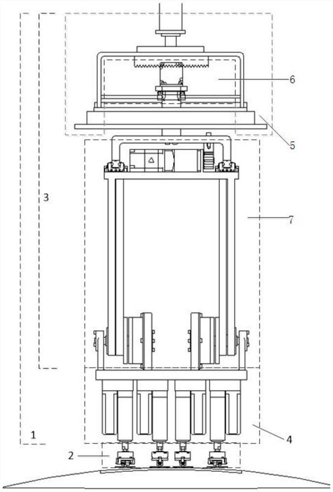
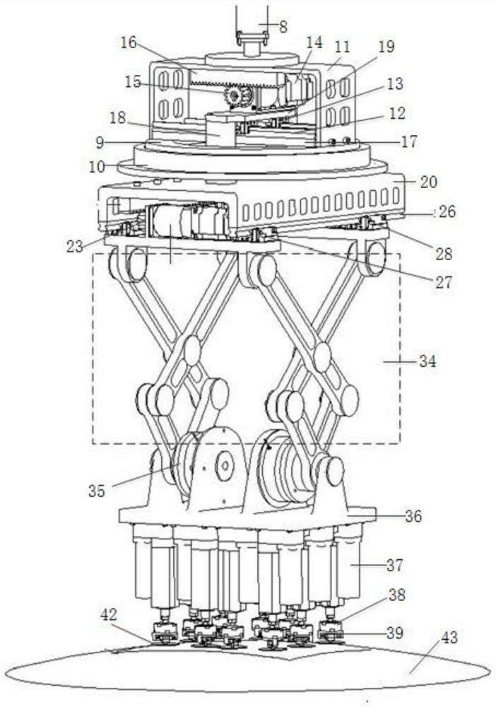
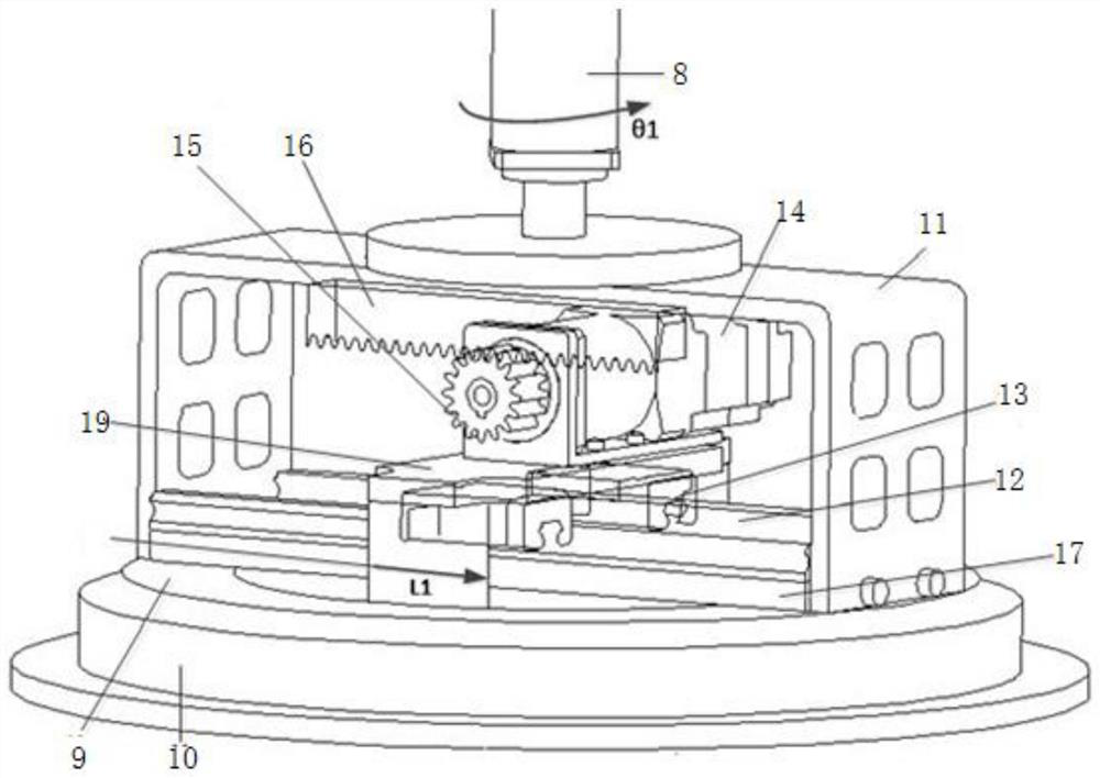
[0030] Such as Figure 1-Figure 9 As shown: this embodiment provides an adsorption loading and unloading device, including a three-degree-of-freedom feeding mechanism 1 and an adsorption platform 2. The three-degr...


PUM


Abstract

The invention discloses an adsorption loading and unloading device which comprises a three degree-of-freedom feeding mechanism and an adsorption platform, wherein the three degree-of-freedom feeding mechanism comprises a coarse adjustment mechanism and a fine adjustment mechanism; the coarse adjustment mechanism comprises a rotary motion module, a horizontal motion module and a vertical motion module, and the horizontal motion module is arranged on the rotary motion module; the upper end of the vertical motion module is rotationally connected with the horizontal motion module, and the lower end of the vertical motion module is rotationally connected with the fine adjustment mechanism; the rotary motion module, the horizontal motion module and the vertical motion module can respectively drive the fine adjustment mechanism to doe rotary motion, horizontal motion and vertical motion; the adsorption platform is connected with the fine adjustment mechanism; and the lower end of the adsorption platform is used for adsorb an object to be taken. The invention can provide the adsorption loading and unloading device with high-strength adsorption, accurate and rapid positioning, a flexible and adaptive curved adsorption surface and high security, so as to solve the problems of the prior art.

Description

technical field [0001] The invention relates to the technical field of cargo loading and unloading, in particular to an adsorption loading and unloading device. Background technique [0002] In the past 20 years, the loading and unloading of goods has always been a hot spot in the field of cargo handling. Due to the particularity of handling objects such as glass, paper printing, ports and buildings, there are high requirements for mechanical and electrical equipment for loading and unloading. At present, the loading and unloading methods mainly include mechanical meshing, dry and wet adhesion, wire rope lifting, magnetic adsorption, vacuum adsorption and other methods. Compared with mechanical meshing, dry and wet adhesion, wire rope lifting and other methods, the vacuum adsorption loading and unloading method has a corrugated surface that can increase the friction and adsorption capacity of the surface lubricated and airtight workpieces, and does not need to be considered ...

Claims


Application Information

Patent Timeline
Patent Type & Authority Applications(China)
IPC IPC(8): B65G47/91
CPCB65G47/914B65G47/917
Inventor 冯美付强高帅周佳成倪志学公言磊李妍卢秀泉李鹏金星泽
Owner JILIN UNIV
Learn More