
Pouring system for oil passage orifice plate castings

A technology of pouring system and orifice plate, which is applied in the direction of casting mold, casting mold composition, casting molding equipment, etc., can solve problems such as deformation, high production cost, and restrict production efficiency, so as to improve economic benefits, increase production efficiency, and improve molding quality effect

Pending Publication Date: 2020-09-11
ZHANJIANG DENI VEHICLE PARTS
View PDF0 Cites 0 Cited by
  • Summary
  • Abstract
  • Description
  • Claims
  • Application Information

AI Technical Summary

Problems solved by technology

[0002] The oil channel orifice plate of automobile engine has the characteristics of small size, high thickness ratio, high precision and internal quality requirements, etc., especially the strict air hole standard; traditionally, when casting oil channel orifice plate, in order to ensure that the casting can meet the requirements, usually adopt The pouring method of one mold and one cavity, but this will seriously restrict the production efficiency and cause higher production costs
[0003] Moreover, for a specific type of oil channel orifice plate, its maximum thickness during casting is about 30mm, while the thinnest thickness is only about 3mm. Under this structure, conventional casting methods are used for casting , it is very easy to produce die-casting defects such as pores, under-casting, looseness, deformation, etc., and it is difficult to effectively ensure the production quality of castings

Method used


Image

  • Pouring system for oil passage orifice plate castings
  • Pouring system for oil passage orifice plate castings
  • Pouring system for oil passage orifice plate castings

Examples


Embodiment 1

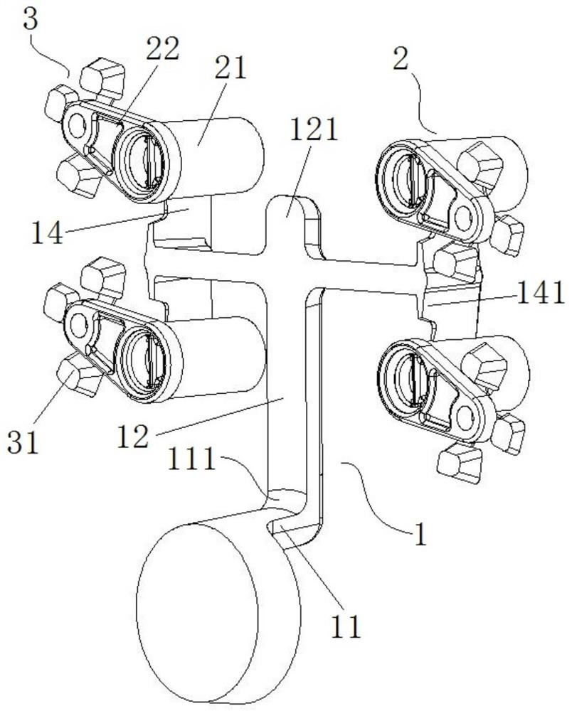
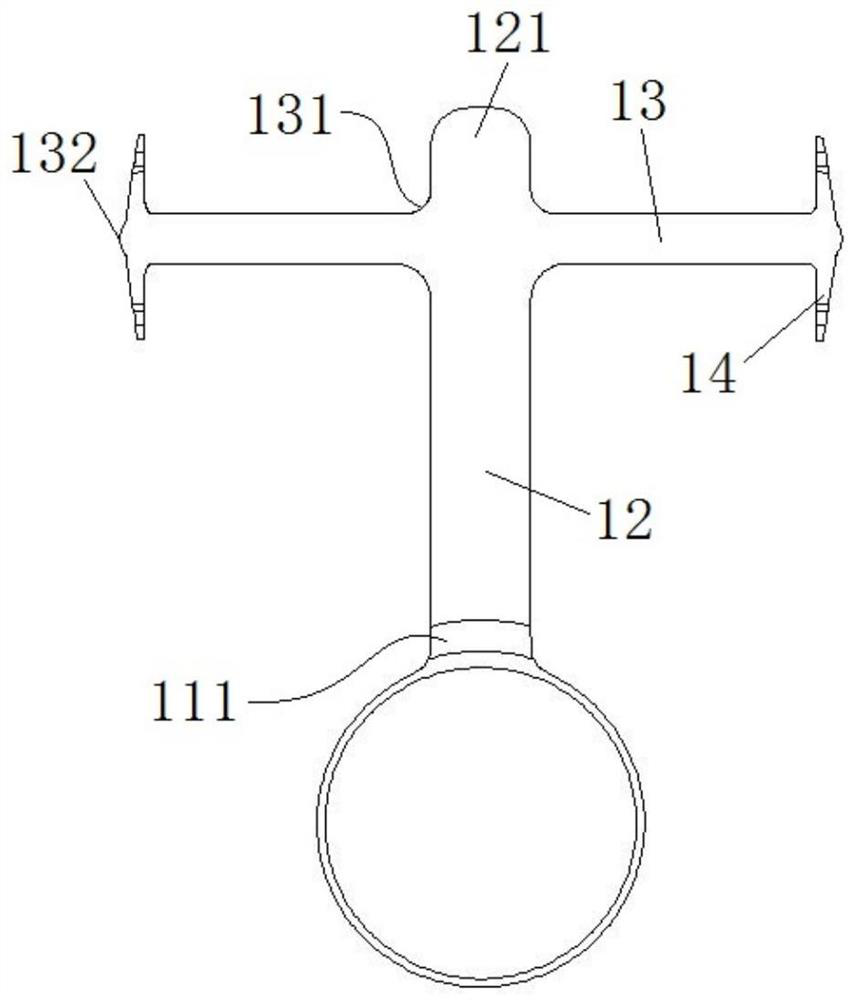
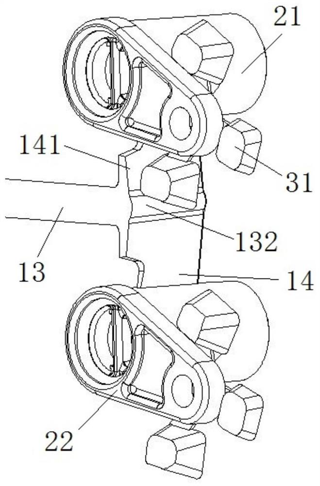
[0035] Such as Figure 1-3 As shown, this embodiment provides a gating system for oil channel orifice castings, which mainly includes a runner system 1, several cavities 2, and an overflow system 3; specifically:

[0036] The runner system 1 includes a straight runner 11 , a runner 12 , a branch runner 13 and a secondary branch runner 14 connected in sequence.

[0037] The head end of the sprue 11 communicates with the gate, and the end of the sprue 11 communicates with the head end of the runner 12 and forms a first bending area 111; as a preferred solution , the sprue 11 and the runner 12 are connected at right angles, and the first bending area 111 is set at the junction of the two to form a smooth transition; in this embodiment, the first bend The fold area 111 is a smooth transition of equal cross-sectional area, including an inner corner and an outer corner formed by bending. The ratio of the radius between the inner corner and the outer corner is greater than or equal ...


PUM


Abstract

The invention provides a pouring system for oil passage orifice plate castings. The pouring system includes a runner system and a plurality of cavities. The runner system includes a straight runner, alateral runner, branch runners and a sub-branch runner. The straight runner communicates with the lateral runner to form a first bending zone, the branch runners are symmetrically arranged on the twosides of the lateral runner in a communicating mode, and first temporary storage areas are formed from communicating positions of the branch runners and the lateral runner to the tail end of the lateral runner. The sub-branch runners are symmetrically arranged on the two sides of the branch runners in a communicating mode, and second temporary storage areas are arranged at the communicating positions of the sub-branch runners and the branch runners. Each cavity includes a cylindrical cavity portion and an annular-plate-shaped cavity portion, gates are arranged on the cylindrical cavity portions in a communicating mode, and the injection direction of the gates does not overlap with the axis of the cylindrical cavities. The production efficiency of the oil passage orifice plate castings canbe effectively improved, the production quality of oil passage orifice plates is greatly improved, and the economic benefits are improved.

Description

technical field [0001] The invention belongs to the technical field of casting of automobile engine parts, and in particular relates to a pouring system for oil passage orifice castings. Background technique [0002] The oil channel orifice plate of automobile engine has the characteristics of small size, high thickness ratio, high precision and internal quality requirements, etc., especially the strict air hole standard; traditionally, when casting oil channel orifice plate, in order to ensure that the casting can meet the requirements, usually adopt The pouring method of one mold and one cavity will seriously restrict the production efficiency and cause higher production costs. [0003] Moreover, for a specific type of oil channel orifice plate, its maximum thickness during casting is about 30mm, while the thinnest thickness is only about 3mm. Under this structure, conventional casting methods are used for casting , It is easy to produce die-casting defects such as pores,...

Claims


Application Information

Patent Timeline
IPC IPC(8): B22C9/08B22C9/22
CPCB22C9/082B22C9/22
Inventor 陈贞军易方富
Owner ZHANJIANG DENI VEHICLE PARTS
Learn More