Full-load denitrification system for boiler deep peak load regulation and operation method thereof

A full-load, denitrification technology, applied in the direction of combustion methods, separation methods, chemical instruments and methods, etc., can solve problems such as low-temperature corrosion of air preheaters, ammonia escape, and emissions that do not meet environmental protection requirements, and achieve increased side effects. The effect of reducing the flue gas flow rate, facilitating renovation and installation, and facilitating system maintenance

Pending Publication Date: 2020-09-11
STATE GRID SHAANXI ELECTRIC POWER RES INST +2
View PDF2 Cites 9 Cited by
  • Summary
  • Abstract
  • Description
  • Claims
  • Application Information

AI Technical Summary

Problems solved by technology

A large number of coal-fired boilers are equipped with SCR (Selective Catalytic Redox Technology) denitrification devices. Due to the inherent characteristics of SCR denitrification devices, there are strict requirements on the reaction temperature (300-420°C). The SCR denitrification device will not be put into normal operation when the lower limit is reached
[0003] In recent years, with the rapid development of distributed clean energy such as wind power and solar power, the main task of most coal-fired power plant boilers with small installed capacity has changed from full-load power generation to peak-shaving operation, and these units have been under low load for a long time operation; it is difficult to reach the optimal smoke temperature of the SCR denitrification device under low load operation, resulting in NO x The discharge volume does not meet the relevant environmental protection requirements, and it will also cause a large amount of ammonia gas to escape. The ammonia gas reacts with sulfide to form sulfuric acid crystals, causing problems such as low-temperature corrosion of the air preheater.

Method used


Image

  • Full-load denitrification system for boiler deep peak load regulation and operation method thereof
  • Full-load denitrification system for boiler deep peak load regulation and operation method thereof

Examples


Embodiment Construction

[0037]In order to make the purpose, technical effects and technical solutions of the embodiments of the present invention more clear, the technical solutions in the embodiments of the present invention are clearly and completely described below in conjunction with the accompanying drawings in the embodiments of the present invention; obviously, the described embodiments It is a part of the embodiment of the present invention. Based on the disclosed embodiments of the present invention, other embodiments obtained by persons of ordinary skill in the art without making creative efforts shall all fall within the protection scope of the present invention.

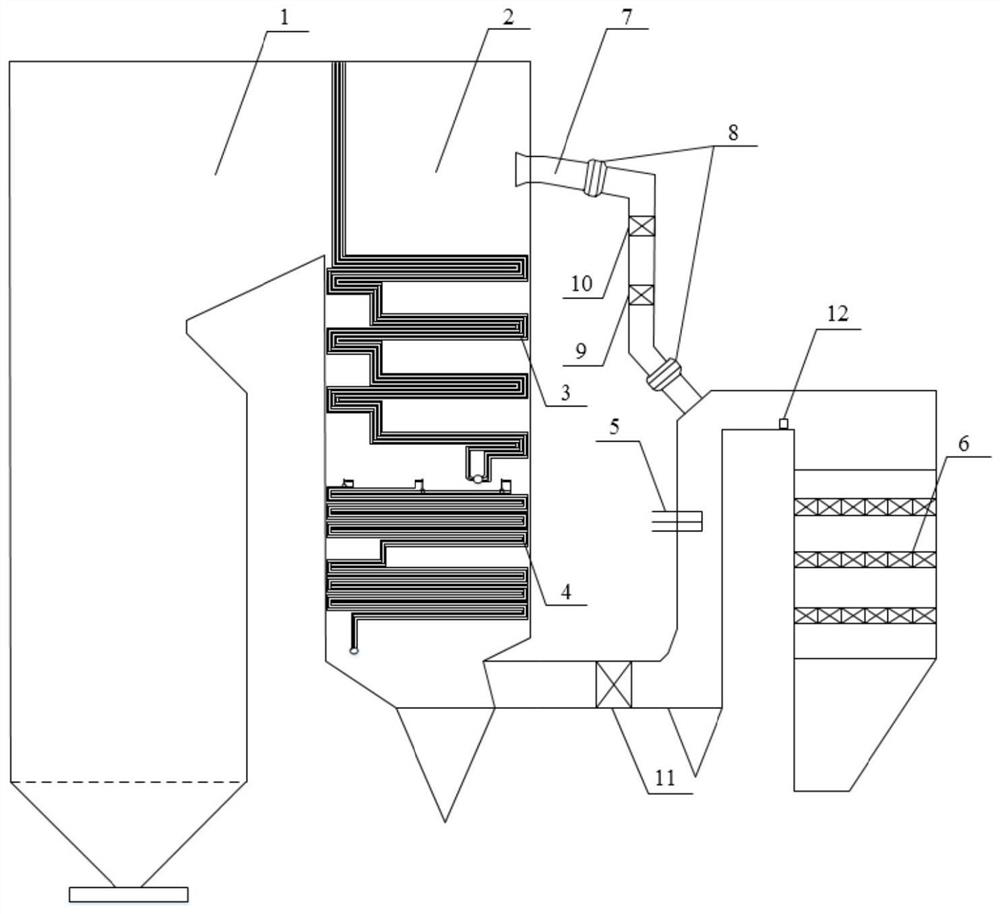
[0038] A full-load denitrification system for deep peak regulation of boilers according to an embodiment of the present invention, including: a boiler 1 sequentially connected through the main flue, a tail smoke well steering chamber 2, a heater 3, an economizer 4, and ammonia gas injection gun 5 and SCR reactor 6;

[0039] Whe...


PUM


Abstract

The invention discloses a full-load denitrification system for boiler deep peak load regulation and an operation method thereof. The system has a structure that a main flue is sequentially provided with a tail flue shaft steering chamber, a heater and an economizer along the flow direction of flue gas; the inlet of a bypass flue is communicated with the tail flue shaft steering chamber, and the outlet of the bypass flue is set on the flue at the entrance of an SCR reactor; the economizer is connected with a water supply pipe; a No.0 high pressure heater, a No.1 high pressure heater, a No.2 high pressure heater, a No.3 high pressure heater, a water supply pump and a deaerator are provided in sequence on the water supply pipe along the opposite direction of water supply; the No.0 high pressure heater is connected with a No.0 high pressure pump-out pipe, and the No.0 high pressure pump-out pipe is provided with a No.0 high pressure pump-out pipe regulating valve. The system provided by the invention can realize the full-load denitrification of a unit and the regulation of the operating flue gas temperature by controlling the flue gas flow rate of the flue gas bypass and coupling and putting the No.0 high pressure heater into operation.

Description

technical field [0001] The invention belongs to the technical field of thermal power flexibility and full-load denitrification, and particularly relates to a full-load denitrification system for deep peak regulation of boilers and an operation method thereof. Background technique [0002] With the continuous reform of environmental protection policies, the emission standards of air pollutants in thermal power plants must achieve ultra-low emissions, and require the investment in denitrification devices under full load conditions. A large number of coal-fired boilers are equipped with SCR (Selective Catalytic Redox Technology) denitrification devices. Due to the inherent characteristics of SCR denitrification devices, there are strict requirements on the reaction temperature (300-420°C). When the lower limit is reached, the SCR denitrification device will not be able to be put into normal operation. [0003] In recent years, with the rapid development of distributed clean en...

Claims


Application Information

Patent Timeline
Patent Type & Authority Applications(China)
IPC IPC(8): F23J15/00F23J15/02F22D1/02B01D53/86B01D53/56
CPCB01D53/56B01D53/8628B01D2258/0283F22D1/02F23J15/006F23J15/02F23J2215/10
Inventor 朱超王永庆吴鹏举李峰张拓朱明辉权琛李壮赵嘉周熙宏杨冬
Owner STATE GRID SHAANXI ELECTRIC POWER RES INST
Why Eureka
Try Eureka