Photovoltaic installation system

An installation system and photovoltaic technology, applied in the field of photovoltaics, can solve the problems of DC cable consumption and high photovoltaic array line loss, etc., achieve the effect of reducing packaging weight, reducing the amount of electrical connection cables, and solving the effect of long threads

Pending Publication Date: 2020-09-11
SUNMAN (ZHENJIANG) CO LTD
View PDF2 Cites 2 Cited by
  • Summary
  • Abstract
  • Description
  • Claims
  • Application Information

AI Technical Summary

Problems solved by technology

Through the patent search, the applicant did not find a technical solution for reducing the loss of the photovoltaic array that electrically connects photovoltaic modules. However, the applicant found that the photovoltaic array needs to connect a large number of photovoltaic modules through cables to achieve current convergence. A photov

Method used


Image

  • Photovoltaic installation system
  • Photovoltaic installation system
  • Photovoltaic installation system

Examples


Embodiment 1

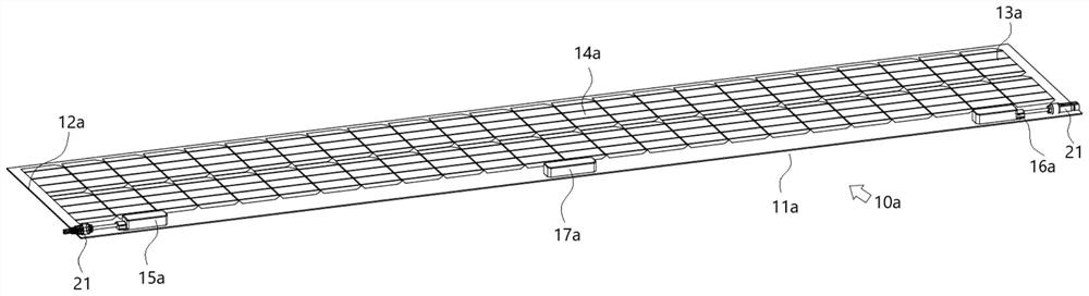
[0065] Example 1: see figure 1 and see in conjunction with Figure 13 As shown, a low line loss photovoltaic array structure includes several photovoltaic modules 10a as photovoltaic array units. Preferably, in this embodiment, the photovoltaic module 10a includes a long side 11a and a wide side 12a; the long side 11a is distributed with 2 photovoltaic cell strings 13a distributed side by side and connected in parallel, wherein each photovoltaic cell string 13a includes 12 (6n, wherein n=2) battery slices 14a connected in series; preferably, in this embodiment, the battery slices 14a adopt 1 / 2 sliced ​​crystalline silicon wafer, this embodiment is referred to as 2 series 1 / 2 sliced ​​photovoltaic module 10a; the single side length of the battery slice 14a is 100-260mm, more preferably, it can be 120-220mm, for example , the unilateral length specification of the entire battery sheet 14a can be 156mm, 158mm, 166mm or 210mm, and the specific specification can be selected accord...

Embodiment 2

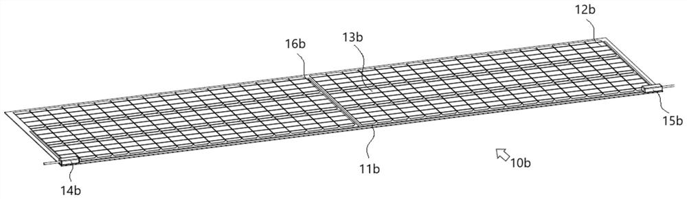
[0071] Embodiment 2: The remaining technical solutions of this embodiment 2 are the same as those of embodiment 1, the difference is that in this embodiment 2, please refer to figure 2In the photovoltaic module 10b shown, three photovoltaic cell strings 12b arranged side by side and connected in series are distributed on the long side 11b, wherein each photovoltaic cell string 12b includes 36 (6n, where n=6) battery sheets 13b connected in series; Preferably, in this embodiment, the cell sheet 13b is a 1 / 3 sliced ​​crystalline silicon sheet, which is referred to as 3 series 1 / 3 sliced ​​photovoltaic modules 10b in this embodiment; The light-receiving surface is respectively provided with a first end-side junction box 14b and a second end-side junction box 15b, the first end-side junction box 14b and the second end-side junction box 15b are located on the same side of the long side 11b, each junction box 14b, 15b They are electrically connected by a bus bar 16b, and no interme...

Embodiment 3

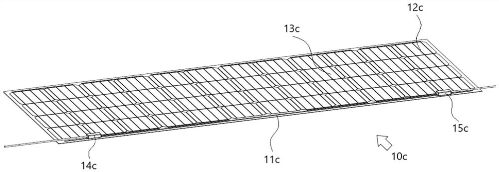
[0072] Embodiment 3: The remaining technical solutions of this embodiment 3 are the same as those of embodiment 1, the difference is that in this embodiment 3, please refer to image 3 In the photovoltaic module 10c shown, there are 12 (6n, where n=2) photovoltaic cell strings 12c arranged in parallel and connected in series on the long side 11c, wherein each photovoltaic cell string 12c includes four series-connected cell sheets 13c; Preferably, in this embodiment, the cell 13c is a monolithic crystalline silicon wafer, which is referred to as the 4-series monolithic photovoltaic module 10c in this embodiment; The first end junction box 14c and the second end junction box 15c, the first end junction box 14c and the second end junction box 15c are located on the same side of the long side 11c, the junction boxes 14c, 15c are connected by a bus bar (not shown in the figure) electrical connection, the present embodiment 3 is not provided with an intermediate junction box; a diod...


PUM


Abstract

The invention discloses a photovoltaic installation system, which comprises an A-type photovoltaic module column formed by connecting at least two A-type photovoltaic modules in series, and a B-type photovoltaic module column formed by connecting at least two B-type photovoltaic modules in series, wherein the A-type photovoltaic module column and the B-type photovoltaic module column are connectedin series and are arranged on a mounting base plane in an alternating parallel arrangement structure, the A-type photovoltaic module column comprises an A-type positive electrode output end located at one end and an A-type negative electrode output end located at the other end, the B-type photovoltaic module column comprises a B-type positive electrode output end located at one end and a B-type negative electrode output end located at the other end, the A-type positive electrode output end and the B-type negative electrode output end are located at the same end, the A-type negative electrodeoutput end and the B-type positive electrode output end are located at the same end, and the A-type negative electrode output end is electrically connected with the B-type positive electrode output end of the adjacent B-type photovoltaic module column through a cable connector. According to the invention, the wiring structure of a long direct current cable thread is effectively avoided, and the line loss of a photovoltaic installation system is obviously reduced.

Description

technical field [0001] The invention belongs to the technical field of photovoltaics, and in particular relates to a photovoltaic installation system. Background technique [0002] Photovoltaic arrays usually refer to photovoltaic power generation products that use multiple photovoltaic modules to connect in series and / or parallel through cable joints to meet the requirements of high-voltage and high-power power generation, and finally transfer current to the inverter through DC cables. , wherein a photovoltaic module is generally a photovoltaic array unit in which several cells are connected in series and / or in parallel through conductive grid lines. [0003] The applicant found that there are many technical solutions for reducing the internal current loss of photovoltaic modules used as photovoltaic array units in the prior art. For example, the use of half-chip or laminated technology can reduce the internal current and internal loss of photovoltaic modules. Through the ...

Claims


Application Information

Patent Timeline
IPC IPC(8): H02S40/34H02S40/36H02S20/25F24S25/613H01L31/048
CPCF24S25/613H01L31/0481H02S20/25H02S40/34H02S40/36Y02B10/10Y02E10/47Y02E10/50
Inventor 崔标施正荣谢涛涛
Owner SUNMAN (ZHENJIANG) CO LTD
Why Eureka
Try Eureka