Anaerobic digestion wastewater treatment equipment

A technology for wastewater treatment and anaerobic digestion, which is used in anaerobic digestion treatment, water treatment parameter control, biological water/sewage treatment, etc. It can solve the problems of lack of intelligence, occupying space, slow response, etc., and achieve convenient and fast operation. , the structure is simple, the effect of accelerated reaction

Pending Publication Date: 2020-09-15
杭州迦北科技有限公司
View PDF13 Cites 0 Cited by
  • Summary
  • Abstract
  • Description
  • Claims
  • Application Information

AI Technical Summary

Problems solved by technology

[0004] The purpose of the present invention is to provide a kind of anaerobic digestion waste water treatment equipment, to solve the above-mentioned background technology for the present anaerobic digestion waste water treatment, it is to adopt the above-ground tank body treatment, so that the volume is relatively large Occupying space, when anaerobic digestion is performed, it is necessary to put additives into the tank to assist the reaction, and to open the cover when feeding materials causes pollution to the environment and the staff, which is not conducive to the environmental purification index of the current wastewater treatment. During the reaction, due to the insufficient mixing of the wastewater itself, the reaction at the surface of the wastewater is relatively comprehensive, and the bottom surface reacts slowly, which makes the reaction treatment not uniform enough. At the same time, due to the presence of solid substances during the discharge, the pipeline is blocked when the discharge is discharged, resulting in the termination of the sewage discharge. Now Dealing with the problem that the manual operation makes it not intelligent, which is not conducive to the needs of the current social development

Method used


Image

  • Anaerobic digestion wastewater treatment equipment
  • Anaerobic digestion wastewater treatment equipment
  • Anaerobic digestion wastewater treatment equipment

Examples


Embodiment Construction

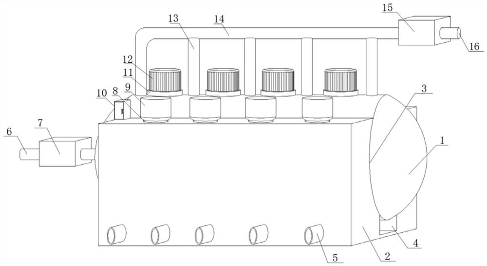
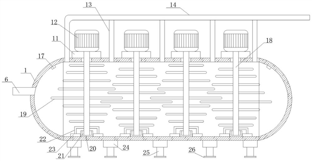
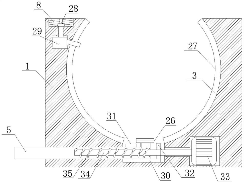
[0027] see Figure 1-2 , 7. In the embodiment of the present invention, an anaerobic digestion wastewater treatment equipment includes a main treatment tank 1, the outer side of the main treatment tank 1 is docked with a supporting outer plate 2, and the inner side of the supporting outer plate 2 is horizontally provided with The clamping groove 3, the main processing tank 1 is arranged horizontally and horizontally, the supporting outer plate 2 is made of concrete material, and the main processing tank 1 is horizontally clamped on the inner side of the clamping groove 3 at the center of the supporting outer plate 2, and the clamping The slot 3 is horizontally opened on the support outer plate 2 and runs through both ends of the support outer plate 2 to the outer side, and the locking slot 3 runs through the top surface of the support outer plate 2 and extends to the outer side. The bottom surface is vertically and horizontally opened with an extension groove 4, and the side o...


PUM


Abstract

The invention discloses anaerobic digestion wastewater treatment equipment, and relates to the field of digestion wastewater. The equipment comprises a main treatment tank, the outer side edge of themain treatment tank is in butt joint with a supporting outer plate; a clamping groove is horizontally formed in the inner side edge of the supporting outer plate. An extending groove is vertically, downwards and horizontally formed in the bottom surface of the clamping groove; blowdown pipes are uniformly inserted into the side edge of the supporting outer plate, a feeding pipeline is horizontallyinserted into one end of the main treatment tank, a feeding valve is in bolted connection with the outer side edge of the feeding pipeline, butt joint screw holes are uniformly formed in the top surface of the supporting outer plate, and a feeding tank is in threaded connection with the inner side edges of the butt joint screw holes. The device is simple in design structure and convenient and fast to operate, the space is not occupied by adopting sunken treatment, meanwhile, stirring is performed during treatment so that the reaction is more sufficient, the reaction effect of internal wastewater is accelerated, and sewage discharge is efficiently completed by adopting the design of pushing accelerated sewage discharge, and the working efficiency is improved.

Description

technical field [0001] The invention relates to the technical field of digestion wastewater treatment, in particular to anaerobic digestion wastewater treatment equipment. Background technique [0002] Anaerobic digestion refers to the digestion technology in which organic matter is decomposed into CH4, CO2, H2O and H2S by facultative bacteria and anaerobic bacteria under anaerobic conditions. Anaerobic digestion is widely used in sewage, livestock and poultry manure and urban organic waste treatment. Biogas engineering technology can achieve the goals of circular economy development, environmental protection, reduction of greenhouse gas emissions and production of renewable energy. Anaerobic digestion technology is one of the most important biomass energy utilization technologies. It converts solid organic matter into dissolved organic matter, and then converts the energy stored in waste into biogas for combustion or power generation, so as to realize the utilization of res...

Claims


Application Information

Patent Timeline
IPC IPC(8): C02F3/28C02F101/30
CPCC02F3/2866C02F2101/30C02F2209/42
Inventor 陈婷婷
Owner 杭州迦北科技有限公司
Why Eureka
Try Eureka