Industrial waste gas desulfurization, denitrification and dust removal equipment

A technology of desulfurization, denitrification, and dust removal equipment, which is applied in the fields of filtration of dispersed particles, transportation and packaging, separation of dispersed particles, etc., which can solve the problems of inconvenient dust particle collection and rapid removal, poor treatment effect and filtration and dust removal effect, and poor treatment effect and filtration effect. and other problems, to achieve the effect of facilitating centralized collection and rapid removal, improving the effect of treatment and reaction, and being beneficial to use.

Inactive Publication Date: 2020-09-18
孙琳
View PDF6 Cites 21 Cited by
  • Summary
  • Abstract
  • Description
  • Claims
  • Application Information

AI Technical Summary

Problems solved by technology

[0003] But the existing industrial waste gas desulfurization, denitrification and dedusting equipment is not convenient for rotating spray treatment liquid and synchronous vibrating filter screen, and its treatment effect and filtering effect are relatively poor, (mainly reflected in the simple way that the treatment liquid is directly poured down and cannot be fully combined with Flue gas contact reaction, and the way of static filtration, dust particles are easy to statically adhere to and block the filter screen, resulting in reduced filtration efficiency of the filter screen due to blockage), the treatment effect and filter dust removal effect are poor, and it is not convenient to concentrate the dust particles Collection and rapid removal cannot meet the needs of use. In view of this phenomenon, we have proposed an industrial waste gas desulfurization, denitrification and dust removal equipment to solve the above problems

Method used


Image

  • Industrial waste gas desulfurization, denitrification and dust removal equipment
  • Industrial waste gas desulfurization, denitrification and dust removal equipment
  • Industrial waste gas desulfurization, denitrification and dust removal equipment

Examples


Embodiment

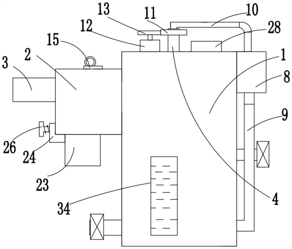
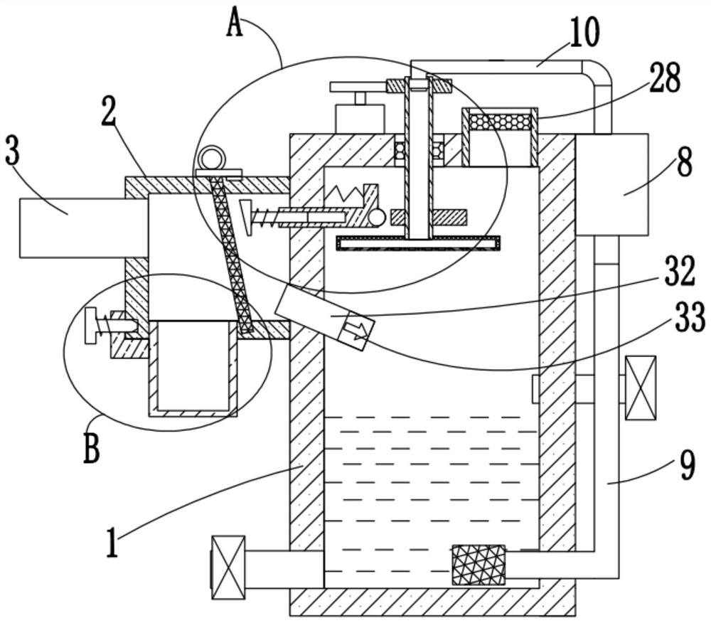
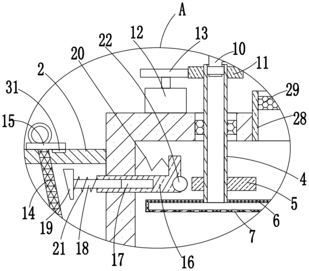
[0028] refer to Figure 1-5, this embodiment proposes an industrial waste gas desulfurization, denitrification and dust removal equipment, including a reaction box 1, the left bottom of the reaction box 1 is connected and fixed with a drain pipe, and the right side of the reaction box 1 is connected and fixed with a water inlet pipe, a drain pipe and The ends of the water inlet pipes far away from each other are connected and fixed with valves. The reaction box 1 is filled with processing liquid. The shower reaction mechanism comprises a vertical pipe 4 that is installed on the top inner wall of the reaction box 1, and the bottom end of the vertical pipe 4 is communicated with and fixed with a horizontal pipe 6 that both ends are a blocking mechanism, and the bottom inner wall of the horizontal pipe 6 is provided with A plurality of water outlet holes 7, the top of the standpipe 4 extends to the top of the reaction box 1, the first gear 11 located above the reaction box 1 is f...


PUM


Abstract

The invention discloses industrial waste gas desulfurization, denitrification and dust removal equipment. The equipment comprises a reaction box, the bottom of the left side of the reaction box is communicated with and is fixed with a drainage pipe, the right side of the reaction box is communicated with and is fixedly provided with a water inlet pipe, the ends, away from each other, of the drainage pipe and the water inlet pipe are communicated with and are fixedly provided with valves, the reaction box is filled with a treatment liquid, and the reaction box is provided with a rotary sprayingreaction mechanism and an efficient filtering and dust removing mechanism matched with the rotary spraying reaction mechanism. The design is reasonable, rotary spraying of the treatment liquid and synchronous vibration of the filter screen are facilitated, in a rotary spraying state, the sprayed treatment liquid can be uniformly dispersed in the reaction box, the dead angle phenomenon is reduced,the treatment reaction effect is improved, dust particles can be effectively prevented from adhering, accumulating and blocking the filter screen under the oscillation effect, the filtering efficiency is improved, the dust particles can be conveniently collected in a centralized manner and quickly taken out, and the use is facilitated.

Description

technical field [0001] The invention relates to the technical field of desulfurization, denitrification and dust removal equipment, in particular to an industrial waste gas desulfurization, denitration and dust removal equipment. Background technique [0002] With the progress of the society and the development of the economy, there are more and more various power station boilers, industrial kilns, electric arc furnaces, especially coal-fired industrial boilers. Correspondingly, the burden on the environment has increased and the air pollution has become increasingly serious. Various environmental protection laws and regulations have also been gradually promulgated to meet the increasingly harsh environmental protection needs; coal is the main energy source in my country, and the accompanying pollution problems of sulfur dioxide and acid rain will become more prominent. Sulfur, chlorine, and nitrogen oxides produced by coal combustion are atmospheric pollutants. The main sourc...

Claims


Application Information

Patent Timeline
Patent Type & Authority Applications(China)
IPC IPC(8): B01D53/78B01D53/60B01D46/12B01D46/10B01D46/00B01D53/04
CPCB01D53/78B01D53/60B01D46/10B01D46/12B01D53/04B01D46/76
Inventor 孙琳
Owner 孙琳
Why Eureka
Try Eureka