Control method of spinning pressure in spin forming and control system applied by same

A spinning forming and control method technology, applied in the direction of presses, forming tools, manufacturing tools, etc., can solve the problems of product wall thickness thinning area, bulging, and unpredictable changes in material thickness, so as to improve the technical level and forming efficiency , expand the range interval, and control the effect of simple process

Inactive Publication Date: 2020-09-18
AOKEN CNC EQUIP SUZHOU CO LTD
View PDF5 Cites 2 Cited by
  • Summary
  • Abstract
  • Description
  • Claims
  • Application Information

AI Technical Summary

Problems solved by technology

However, in the spinning process with complex shape changes or many forming passes, the change in material thickness is difficult to predict and the wall thickness is different everywhere, so the preset trajectory is different from the actual trajectory. If spinning The wheel only operates on the preset trajectory for position control. If the gap is larger than the wall thickness of the part, the surface of the product will not be smooth. If the gap is smaller than the wall thickness of the part, it will easily cause vibration of the machine tool. The same surface quality is poor or even the material is broken.
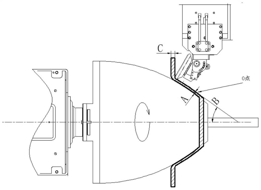
[0004] For further examples, see figure 1 The schematic diagram of the shear spinning forming structure of a certain type of engine nozzle is shown, the material is stainless steel, the thickness is 12mm, and the product thickness at each place is the material thickness * the SIN value of the tangent square at this place: A=C*sin(B); A is the thickness of the product, C is the thickness of the raw material, and B is the unilateral angle of the tangent line at point O; since the tangent angle at each point of the arc has been changing continuously, the preset estimation needs to take a considerable number of points on the arc surface to preset Every gap, the workload is heavy, and it is difficult to control
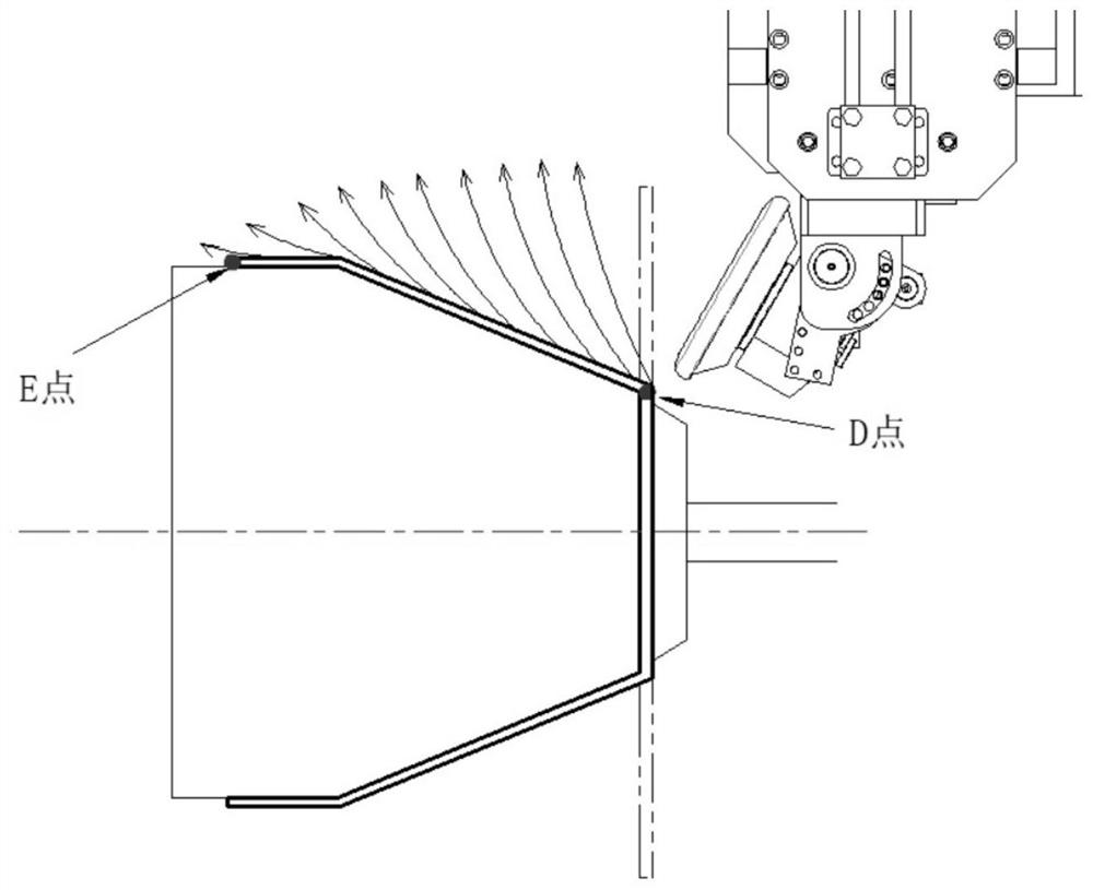
see figure 2 It shows the multi-pass spinning forming structure. Since there are many spinning passes of the material, the number of times of spinning the material from point D to point E after forming is different, and the thickness of the material is also different. Generally, after spinning, it needs to go from point D to point E. A continuous trajectory shaping is also required to obtain a good product surface. Also, due to the different thicknesses everywhere, the preset gap is also difficult to predict
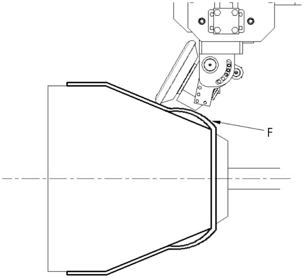
see further image 3 As shown, for the formed product, if the clearance control is too large when shaping again, the purpose of shaping cannot be achieved because the spinning wheel cannot exert effective pressure on the product wall thickness. If the clearance control is too small, it is easy to make the product The thinning of the wall thickness causes the area to be too large to form a bulge F

Method used


Image

  • Control method of spinning pressure in spin forming and control system applied by same
  • Control method of spinning pressure in spin forming and control system applied by same
  • Control method of spinning pressure in spin forming and control system applied by same

Examples


Embodiment 1

[0044] Embodiment 1: The selected material specifications are as follows:

[0045] Brand: 3A21 aluminum plate;

[0046] Thickness: 2mm;

[0047] Shape: conical body with a unilateral angle of 20 degrees;

[0048] State: O state;

[0049] Tensile strength σb (MPa): 120-160;

[0050] Spinning wheel diameter: R8mm;

[0051] According to the spinning pressure control method proposed in this embodiment Figure 9 The 10-pass forming process is carried out by spinning to obtain Figure 10 The molding pass-spinning pressure curve table shown, through Figure 10 It can be seen that when the spinning force is 130kg, the material has a good shape change and the thickness change is negligible.

[0052] It should be noted that in the forming pass-spinning pressure curve table of the present application, the abscissa is the time corresponding to each pass, and the ordinate is the spinning pressure value measured by the strain gauge. It is reflected as pulling force and pushing force...

Embodiment 2

[0053] Embodiment 2: the selected material specifications are as follows:

[0054] Brand: 3A21 aluminum alloy;

[0055] Thickness: 5mm

[0056] State: H1 state;

[0057] Hardness: HL;

[0058] Spinning wheel diameter: R8mm;

[0059] pass Figure 11 It can be seen that when the spinning force is 500kg, the material has a good shape change and the thickness change is negligible.

Embodiment 3

[0060] Embodiment 3: the selected material specifications are as follows:

[0061] Brand: SPHE carbon plate;

[0062] Thickness: 6mm;

[0063] State: Annealed

[0064] Tensile strength (σb / MPa): ≥270

[0065] Spinning wheel diameter: R5mm;

[0066] pass Figure 12 It can be seen that when the pressure is 1200kg, the material has a good shape change and the thickness change is negligible.

[0067] These data directly provide the preferred preset target pressure data reference for the subsequent spinning of these materials.


PUM

PropertyMeasurementUnit
thicknessaaaaaaaaaa
thicknessaaaaaaaaaa
thicknessaaaaaaaaaa

Abstract

The invention discloses a control method of a spinning pressure in spin forming and a control system applied by same. The control method comprises the following steps of by taking preset tracks as driving targets by spinning wheels for spin forming of a material in multiple passes, wherein the spinning wheels carry out curve interpolation to achieve position control through linked driving controlof an X-axis servo driving unit and a Y-axis servo driving unit; in spinning of at least final pass, by taking a separation distance between each spinning wheel and a driving rotary die which is 0 asa driving target, executing double modes of pressure control and position control to the spinning wheels, wherein when the thrusts of the spinning wheels reach a preset target pressure, pressure control is carried out on the spinning wheels to ensure that the separation distance between each spinning wheel and the driving rotary die is 0. The invention further relates to the control system appliedby the control method. By arranging the specific control method and control system, the technical level and the forming efficiency of spin forming are improved effectively.

Description

technical field [0001] The invention belongs to the field of spinning forming technology, and in particular relates to a method for controlling spinning pressure in spinning forming, and also relates to a control system applied to the control method. Background technique [0002] Spinning forming technology is a typical representative process of chipless processing. It is widely used in military industry, aerospace, wind power, petrochemical and other fields. At present, especially in the military industry, it is especially used in the molding of missile bodies, artillery shell bodies, warheads, and shell casings. In terms of engine skins, propeller caps, nozzles, large tanks and medical barrels for pharmaceutical and chemical industries, they all have broad application prospects. However, domestic research on spinning forming technology has only had some preliminary development in recent years. [0003] At present, traditional CNC spinning equipment usually adopts two meth...

Claims


Application Information

Patent Timeline
Patent Type & Authority Applications(China)
IPC IPC(8): B21D22/14B21D37/00B30B15/26
CPCB21D22/14B21D37/00B30B15/26
Inventor 张建利
Owner AOKEN CNC EQUIP SUZHOU CO LTD
Why Eureka
Try Eureka