Quick humidification and semi-digestion method for dedusting dust
A fast and stirring tank technology, which is applied in the direction of instruments, measuring devices, scientific instruments, etc., can solve the problems of serious crushing, the steelmaking dust removal ash spherical body cannot withstand the impact force, and the converter can no longer be used for smelting, so as to increase the production cost, Improves the wetting speed and facilitates chemical reactions
- Summary
- Abstract
- Description
- Claims
- Application Information
AI Technical Summary
Problems solved by technology
Method used
Image
Examples
Embodiment 1
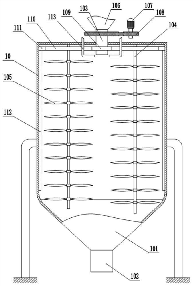
[0036] Embodiment 1 is basically as attached figure 1 and figure 2 Shown:
[0037] A quick humidification and semi-digestion method for dedusting dust. In this method, a stirring tank is used to complete the humidification and semi-digestion treatment of steelmaking dedusting ash, and at the same time, it is mixed with iron oxide scale or magnetic separation powder. The stirring tank includes a support frame and a tank body 10, the tank body 10 is fixed on the support frame, the top of the tank body 10 is in a closed state, an inverted tapered section 101 is welded at the bottom of the tank body 10, and a discharge pipe 102 is welded at the bottom of the inverted tapered section 101, and the inside of the discharge pipe 102 An opening and closing valve is provided, and a stirring mechanism is provided in the tank body 10 .
[0038] In this embodiment, the stirring mechanism includes a hollow shaft 103 and a plurality of stirring rods 104 that are rotatably connected to the ...
Embodiment 2
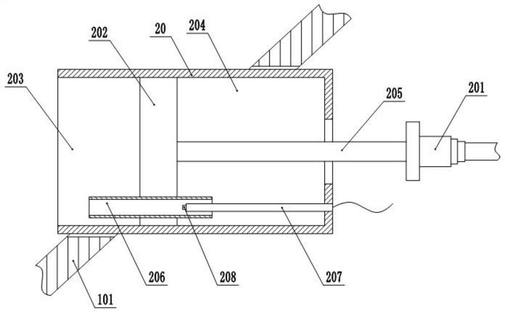
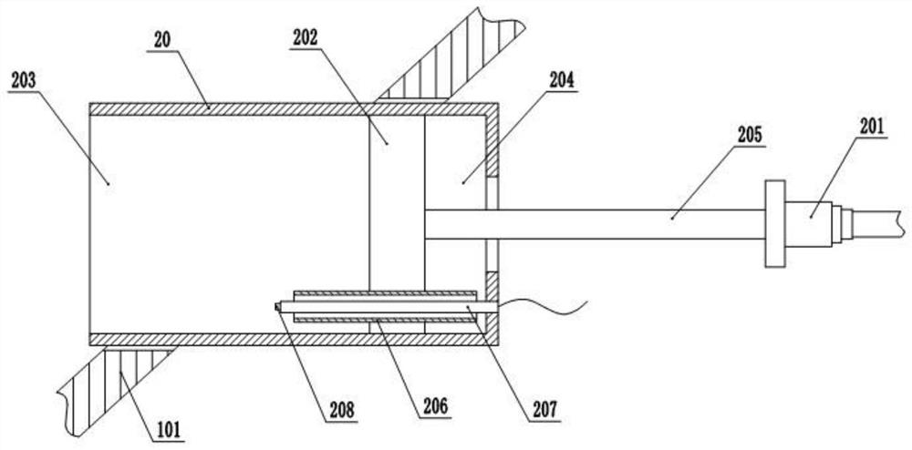
[0046] Embodiment 2 is basically as attached figure 2 and image 3 Shown:
[0047] The difference from Embodiment 1 is that a humidity detection unit is provided on the side wall of the inverted tapered section 101. In this embodiment, the opening and closing valve is a solenoid valve, wherein the solenoid valve is controlled to open and close by the humidity detection unit. In the tank body 10 A mounting hole is provided on the inverted tapered section 101, and the humidity detection unit is fixed in the mounting hole. The humidity detection unit specifically includes a cylinder body 20 and a driver 201, wherein a slider 202 is slidably connected to the cylinder body 20, and the slider 202 will The cylinder body 20 is divided into a sampling chamber 203 and a detection chamber 204. A connecting rod 205 located in the detection chamber 204 is fixed on the slider 202, wherein the driving member 201 drives the connecting rod 205 to perform linear reciprocating motion. In this ...
Embodiment 3
[0051] Embodiment 3 is basically as attached Figure 4 Shown:
[0052] The difference from Embodiment 2 is that the detection chamber 204 is a closed chamber, the connecting rod 205 is in sliding and sealing connection with the cylinder body 20, and the side wall of the detection chamber 204 is provided with an inlet check valve 209 and an outlet check valve 210, When the volume in the detection chamber 204 increases and the air pressure decreases, the air intake check valve 209 opens, and the outside air is filled into the detection chamber 204. When the volume in the detection chamber 204 decreases and the air pressure increases, the air outlet is one-way. The valve 210 is opened, the gas in the detection chamber 204 is discharged, and a constant temperature heating element is electrically connected to the detection chamber 204. The heating temperature of the constant temperature heating element is 32-35°C. The strip-shaped groove 211 and the bar-shaped groove 211 are arran...
PUM
 Abstract
Description
Claims
Application Information
 - R&D
- Intellectual Property
- Life Sciences
- Materials
- Tech Scout
- Unparalleled Data Quality
- Higher Quality Content
- 60% Fewer Hallucinations
Browse by: Latest US Patents, China's latest patents, Technical Efficacy Thesaurus, Application Domain, Technology Topic, Popular Technical Reports.
© 2025 PatSnap. All rights reserved.Legal|Privacy policy|Modern Slavery Act Transparency Statement|Sitemap|About US| Contact US: help@patsnap.com


