Roadbed treatment method based on vacuum dewatering combined with dynamic compaction

A treatment method, a vacuum technology, applied in roads, roads, soil protection, etc., can solve the problem that the subgrade cannot meet the long-term operation requirements of the road, and achieve good reinforcement effects, improved compactness, and enhanced reinforcement effects.

Inactive Publication Date: 2020-09-18
厦门中平公路勘察设计院有限公司
View PDF5 Cites 2 Cited by
  • Summary
  • Abstract
  • Description
  • Claims
  • Application Information

AI Technical Summary

Problems solved by technology

The treated roadbed is difficult to meet the long-term operation requirements of the road
[0004] Some existing treatment methods for miscellaneous fill subgrades containing saturated cohesive soils use the combined treatment of pumping and drainage and dynamic compaction. This treatment method improves the compactness of tamping to a certain extent, but this treatment method is generally only applicable to 5-7m foundation pit

Method used


Image

  • Roadbed treatment method based on vacuum dewatering combined with dynamic compaction
  • Roadbed treatment method based on vacuum dewatering combined with dynamic compaction
  • Roadbed treatment method based on vacuum dewatering combined with dynamic compaction

Examples


Embodiment 1

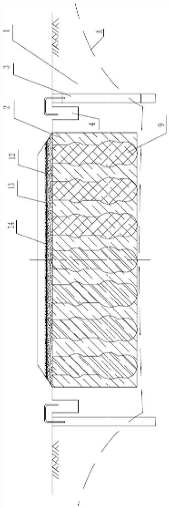
[0039] Such as figure 1 , figure 2 As shown, the present invention discloses a roadbed treatment method based on vacuum precipitation combined with dynamic compaction, comprising the following steps:

[0040] S1. Construction preparation.

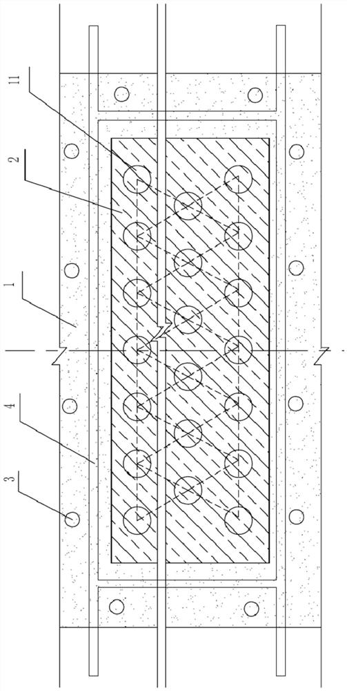
[0041] Clean up and level the ground within the road range, set the precipitation drilling area 1 and the dynamic compaction area 2, the precipitation drilling area 1 surrounds the dynamic compaction area 2, and calculate the subgrade treatment depth according to the road operation requirements.

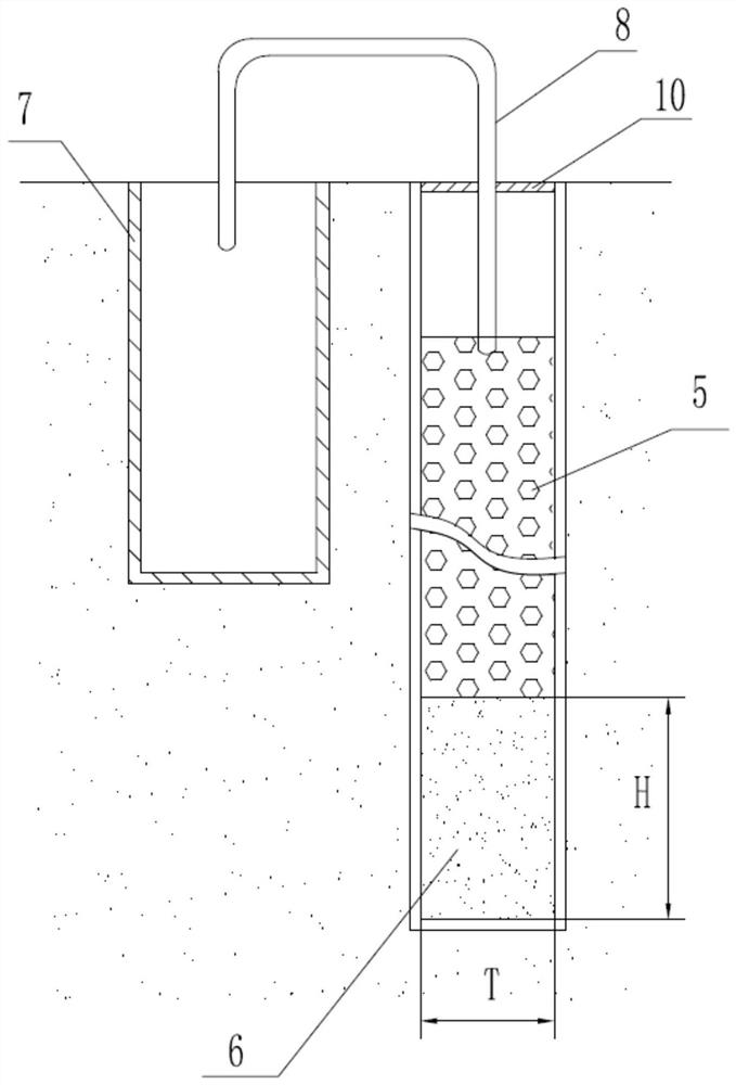
[0042] S2. Borehole buried pipe.

[0043] Such as image 3 As shown, the vacuum dewatering well 3 is set, and the diameter T of the vacuum dewatering well 3 is set to 0.5-0.8m. The well depth is determined according to the depth of the roadbed treatment. 3 to determine the well spacing. On-site stakeout determines the position of the vacuum dewatering well 3, and the mechanical drilling is formed into the well body of the vacuum dewatering w...

Embodiment 2

[0056] The difference between this embodiment and the first embodiment is that the specific steps of step S3 of dynamic compaction filling are different from those of the first embodiment. The process of dynamic compaction filling in the present embodiment is as follows:

[0057] (1) Carry out wire laying and distribution in the dynamic compaction area 2, and pour part of the reinforcing body 9 above each distribution point.

[0058] (2) Use a tamper to ram the reinforcing body 9, so that the reinforcing body 9 sinks and squeezes the soil layer to both sides.

[0059] (3) After the reinforcing body 9 sinks until the site is level, continue to pour the reinforcing body 9 above the distribution point.

[0060] (4) Steps (2) and (3) are repeated for tamping with a rammer until the reinforcing body is tamped to the depth of the subgrade treatment.

[0061] (5) The site is treated with full compaction, and the rammers overlap each other to form a strong compaction reinforcement l...


PUM


Abstract

The invention discloses a roadbed treatment method based on combination of vacuum dewatering and dynamic compaction. The roadbed treatment method comprises the following steps: S1, construction preparation; s2, hole drilling and pipe burying: holes are drilled in the precipitation drilling area, a vacuum dewatering well is arranged, a drainage ditch is arranged near the vacuum dewatering well, water pumping equipment is installed for water pumping, a water pumping pipe pumps water in the vacuum dewatering well into the drainage ditch, and the underground water level is controlled to be below the roadbed treatment depth; S3, dynamic compaction filling: the soil layer of the dynamic compaction area is evenly tamped and filled with reinforcements, the filling height is the roadbed treatment depth, the reinforcements and the treated soil layer jointly form a dynamic compaction reinforcing layer, and the reinforcements are one or more of hard rock fragments, concrete fragments and construction waste fragments; S4, laying of a structural layer. According to the treatment method, the pore water pressure in the roadbed is reduced, the tamping effect during dynamic compaction is better achieved, post-construction settlement of the roadbed is reduced, and the bearing capacity of the roadbed is effectively improved.

Description

technical field [0001] The invention relates to the technical field of road engineering, in particular to a roadbed treatment method based on vacuum dewatering combined with dynamic compaction. Background technique [0002] Miscellaneous fill is the garbage soil left or piled up by people's living and production activities. These waste soils are generally divided into three categories: construction waste soil, domestic waste soil and industrial production waste soil. It is difficult to describe different types of garbage soils and garbage soils piled up at different times with uniform strength indicators, compression indicators, and permeability indicators. The main characteristics of miscellaneous fill are unplanned accumulation, complex composition, different properties, uneven thickness and poor regularity. Therefore, the same site shows obvious differences in compressibility and strength, which can easily cause uneven settlement. The particle arrangement of saturated ...

Claims


Application Information

Patent Timeline
Patent Type & Authority Applications(China)
IPC IPC(8): E01C3/00E02D3/10E02D3/046
CPCE01C3/00E02D3/10E02D3/046
Inventor 翁子纯易金通陈小江何紫昕林兴奋
Owner 厦门中平公路勘察设计院有限公司
Why Eureka
Try Eureka