Mechanical arm kinematics parameter calibration method based on inertial measurement unit

An inertial measurement unit and kinematic parameter technology, applied in the field of robotics, can solve the problems of high cost, low measurement efficiency, and small quantity, and achieve the effects of simple operation, simplified kinematics calibration steps, and reduced experimental cost.

Active Publication Date: 2020-09-22
HARBIN INST OF TECH
View PDF4 Cites 3 Cited by
  • Summary
  • Abstract
  • Description
  • Claims
  • Application Information

AI Technical Summary

Problems solved by technology

Secondly, the instrument is a non-contact calibration, so it has high requirements on the continuity of the laser, but in practice, the light will often be cut off and re-measurement will be required, resulting in the low measurement efficiency of this method; finally, the current measurement The number of products is small, and the cost is often several million, so the economic performance is poor for small-scale calibration experiments. In addition, in terms of patent literature, CN106799745A, an industrial manipulator arm precision calibration method based on collaborative kriging, discloses a method using The calibration device composed of a laser tracker an

Method used


Image

  • Mechanical arm kinematics parameter calibration method based on inertial measurement unit
  • Mechanical arm kinematics parameter calibration method based on inertial measurement unit
  • Mechanical arm kinematics parameter calibration method based on inertial measurement unit

Examples


Embodiment Construction

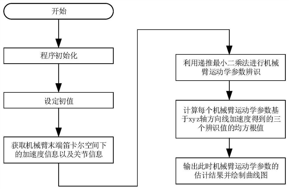
[0025] combine figure 1 Note that this implementation is based on the Jacobian matrix of the manipulator, and the Jacobian matrix is ​​an expression that links the linear velocity in the Cartesian space at the end of the manipulator with the velocity in the joint space, as follows:

[0026]

[0027] In the formula: v and ω represent the linear velocity of the manipulator and the end angular velocity of the manipulator; J is the Jacobian matrix, q represents the joint angle, Indicates the joint angular velocity. Since the kinematic parameters of the manipulator to be estimated have nothing to do with the end angular velocity of the manipulator, this formula does not introduce the end angular velocity.

[0028] In order to establish the relationship expression between the linear acceleration of the end of the manipulator in Cartesian space and the kinematic parameters of the manipulator, it is necessary to derive the expression of the relationship between the linear velocit...


PUM


Abstract

A mechanical arm kinematics parameter calibration method based on an inertial measurement unit comprises the steps that firstly, the relation expression among the linear speed under a mechanical arm tail end Cartesian coordinates, the speed relation under the joint space and the jacobian matrix is constructed, and derivation is conducted; secondly, normalization processing is conducted on the derived relational expression; thirdly, the linear acceleration under the mechanical arm tail end Cartesian space and the angle, the angle speed and the angle acceleration under the mechanical arm joint space are obtained; fourthly, the recursive least-squares method is utilized for conducting mechanical arm parameter identification, and the mechanical arm kinematics parameter calculated value in eachdirection is obtained; and fifthly, the root-mean-square value is obtained from the obtained three values, the mechanical arm kinematics parameter final estimated value at the time is output, and a curve is drawn. By means of the mechanical arm kinematics parameter calibration method, the mechanical arm kinematics calibration cost is reduced. Along with constant improvement of the inertial measurement unit technology, the measuring precision is higher and higher, the precision of the calibration result is higher and higher, and the mechanical arm kinematics parameter calibration method has wider development prospects.

Description

technical field [0001] The invention relates to the technical field of robots, in particular to a method for calibrating kinematic parameters of a manipulator based on an inertial measurement unit. Background technique [0002] There are many factors that affect the positioning accuracy of the end of the industrial robot, and among these errors, the error caused by the geometric parameters is the system error, and it is also the main factor that causes the absolute positioning accuracy of the manipulator to be low. In order not to change the hardware configuration of the manipulator, it is the most economical method to identify the kinematic parameters of the manipulator. [0003] In the model-based kinematics calibration method of the manipulator, end effectors are needed, such as laser tracker, three-coordinate measuring instrument, ballbar and so on. Newman W S et al. completed the kinematic calibration of the P8 robot with a laser tracker. Rencheng Wang et al. only inst...

Claims


Application Information

Patent Timeline
IPC IPC(8): B25J9/16B25J19/00
CPCB25J9/1653B25J9/1692B25J19/0095
Inventor 金弘哲赵杰周睿张慧龙奕琳
Owner HARBIN INST OF TECH
Why Eureka
Try Eureka