Flue gas utilization system, flue gas utilization process and high-temperature combustion treatment system

A high-temperature combustion and treatment system technology, applied in the direction of waste heat treatment, combustion method, combustion type, etc., can solve the problems of adding heat source, high energy consumption of the system, insufficient flue gas combustion, etc., to achieve small negative pressure loss and optimize the system structure, cost-saving effect

Pending Publication Date: 2020-09-22
INNER MONGOLIA PURUIFEN ENVIRONMENTAL SCI ANDTECH
View PDF5 Cites 3 Cited by
  • Summary
  • Abstract
  • Description
  • Claims
  • Application Information

AI Technical Summary

Problems solved by technology

[0006] The purpose of the present invention is to solve the above problems, provide a flue gas utilization system, a flue gas utilization process, and a high-temperature combustion treatment system, to solve the problem that the combustion chamber of the high-temperature combustion treatment system needs to continuously add heat sources, the system consumes high energy consumption, and the flue gas combustion in the combustion chamber Insufficient and optimized overall flue gas treatment equipment layout and other issues

Method used


Image

  • Flue gas utilization system, flue gas utilization process and high-temperature combustion treatment system
  • Flue gas utilization system, flue gas utilization process and high-temperature combustion treatment system
  • Flue gas utilization system, flue gas utilization process and high-temperature combustion treatment system

Examples


Embodiment approach

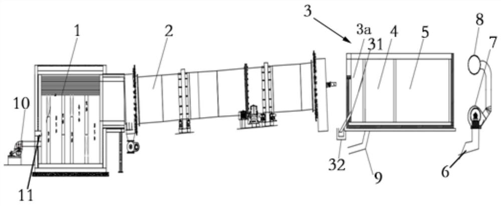
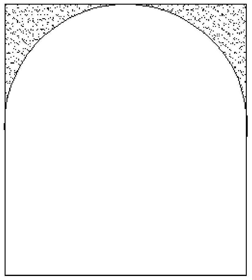
[0070] combine figure 1 with figure 2 As shown, according to one embodiment of the present invention, the return flue 9 is a hollow thermal insulation channel, which can be set as a pipeline containing thermal insulation or refractory thermal insulation materials, or a storage tank built with refractory bricks inside and wrapped with thermal insulation or thermal insulation materials. Thermal piping. According to the second embodiment of the present invention, the return flue 9 is an underground flue, that is, part of the return flue 9 is set underground. In this embodiment, the height of the return flue 9 is 1.2-1.5m, and the width is 0.6-0.8m. The top of the return flue 9 is set in an arched structure, and the elbow is set in an arc shape. The arched design at the top of the return flue 9 and the arc-shaped arrangement at the elbow of the present invention optimize the structure of the return flue 9 and help reduce the return resistance of the flue gas. The return flue 9...


PUM

PropertyMeasurementUnit
heightaaaaaaaaaa
widthaaaaaaaaaa

Abstract

The invention relates to a flue gas utilization system, a flue gas utilization process and a high-temperature combustion treatment system. The flue gas utilization system is applied to the high-temperature combustion treatment system, the high-temperature combustion treatment system comprises a combustion chamber and a rotary kiln, wherein the combustion chamber is provided with a natural gas burner and an air distribution device. The flue gas utilization system comprises a flue gas settling device, a discharge flue, a high-temperature induced draft fan, an outlet flue, a return flue and a return fan, wherein the return flue communicates with the flue gas settling device, and the return fan arranged on the combustion chamber introduces part of flue gas in the flue gas settling device intothe combustion chamber of the high-temperature combustion treatment system from the return flue to combust combustible volatiles in the flue gas so as to generate heat. The flue gas utilization systemcan effectively solve the problems that an existing rotary kiln is high in energy consumption, a combustion chamber needs to be continuously provided a heat source, flue gas in an incineration chamber is insufficient in combustion, flue gas is not effectively utilized, and flue gas enters the combustion chamber and is difficult to ignite, and can be applied to the carbonization process of activated carbon to produce activated carbon.

Description

technical field [0001] The invention belongs to the field of flue gas utilization, and in particular relates to a flue gas utilization system, a flue gas utilization process and a high-temperature combustion treatment system. Background technique [0002] In the field of coal-based activated carbon production technology, the flue gas produced in the traditional rotary kiln contains a large amount of flammable volatiles. The heat generated by incineration in the incinerator enters the waste heat boiler for work recovery, and is then discharged after being treated by the denitrification system and the desulfurization and dust removal system. [0003] The incinerators in the prior art are huge in volume, the flue gas stays for a long time and complete combustion cannot be guaranteed. In addition, an economizer or cooling device is usually added at the tail of the waste heat boiler to perform heat exchange treatment, recover flue gas waste heat and reduce flue gas temperature. ,...

Claims


Application Information

Patent Timeline
Patent Type & Authority Applications(China)
IPC IPC(8): F27B7/20F27D17/00F23G7/06F27B7/34F27B7/42C01B32/39
CPCC01B32/39F23G7/06F23G2206/20F23G2209/14F27B7/20F27B7/34F27B7/42F27D17/002F27D17/004F27D17/008F27D2017/006Y02P10/143
Inventor 乔骊竹张振彭汉忠尚永飞于海清赵清朱小龙李婷
Owner INNER MONGOLIA PURUIFEN ENVIRONMENTAL SCI ANDTECH
Why Eureka
Try Eureka