Wire drawing equipment and method for large-core-diameter single-polarization optical fiber

A single-polarization fiber, large core diameter technology, used in glass fiber drawing equipment, glass manufacturing equipment, glass fiber products, etc., can solve the problem of easy burnout, excessive fiber warpage end face, waste of energy consumption, optimization of quartz and stress element uniformity And other issues

Pending Publication Date: 2020-09-25
上海传输线研究所
View PDF0 Cites 0 Cited by
  • Summary
  • Abstract
  • Description
  • Claims
  • Application Information

AI Technical Summary

Problems solved by technology

However, this wire drawing process mainly has two defects. One is that the shape of the preform is not uniform due to the existence of stress elements. The element is mainly composed of boron-doped quartz with a low melting point, and the heating of the annular heating furnace not only wastes energy consumption but also is unfavorable for optimizing the uniformity of the quartz and the stress element; , Insufficient duration, resulting in uneven residual stress inside the optical fiber
Optical fibers with uneven internal stress or structural defects will cause excessive warping of the optical fiber and cracks on the end face during cutting, which will lead to

Method used


Image

  • Wire drawing equipment and method for large-core-diameter single-polarization optical fiber
  • Wire drawing equipment and method for large-core-diameter single-polarization optical fiber
  • Wire drawing equipment and method for large-core-diameter single-polarization optical fiber

Examples


Embodiment 1

[0044] Embodiment 1: In this embodiment, a preform rod with a rod diameter of 29.6 mm is drawn into a double-clad optical fiber.

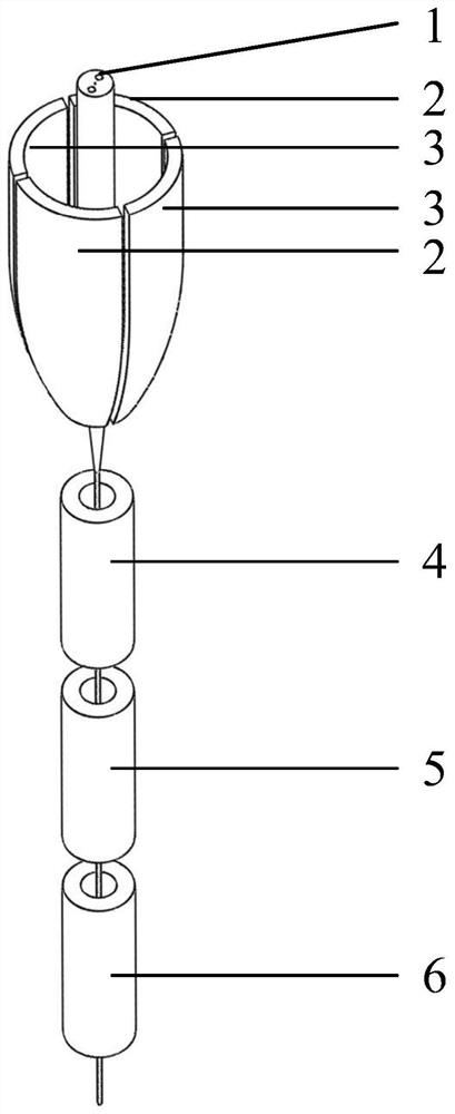
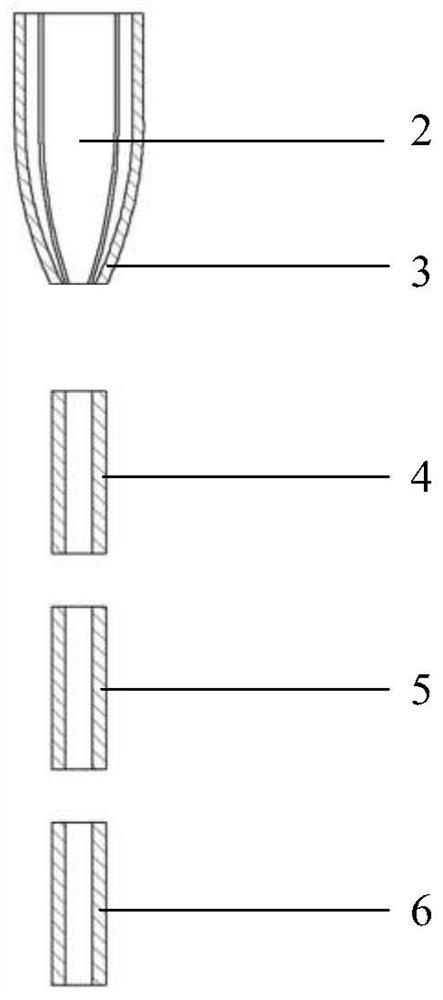
[0045] In this implementation, the arc length ratio of the low temperature zone 2 of the wire drawing furnace to the high temperature zone 3 of the wire drawing furnace is 1:1, both of which are composed of a wire drawing furnace sheet whose temperature can be adjusted. The annealing tube is composed of two pieces, the lengths of the high temperature annealing tube 4 and the low temperature annealing tube 6 are 80 cm and 150 cm respectively, and the temperatures are 800°C and 100°C respectively. See Example 1 in Table 1 for the rest of the parameters.

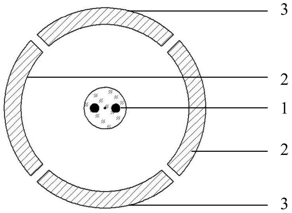
[0046] Step 1. Place the single-polarized optical fiber preform in the drawing furnace by clamping and hoisting. The direction of the line connecting the center of the stress element 1 is aligned with the central axis of the low-temperature zone 2 of the drawing furnace, and the vertical direction i...

Embodiment 2

[0052] Embodiment 2: In this embodiment, a preform rod with a rod diameter of 28.9 mm is drawn into a double-clad optical fiber.

[0053] In this implementation, the arc length ratio between the low-temperature zone 2 of the drawing furnace and the high-temperature zone 3 of the drawing furnace is 1:2, the low-temperature zone 2 of the drawing furnace is composed of one piece of drawing furnace, and the high-temperature zone 3 of the drawing furnace is composed of two pieces of drawing furnace placed side by side. The annealing tube consists of 3 pieces, the lengths of the annealing tube 4, the annealing tube 5 and the annealing tube 6 are 80 cm, 100 cm and 150 cm respectively, and the temperatures are 1000°C, 700°C and 200°C respectively. See Example 2 in Table 1 for the rest of the parameters

[0054] Step 1. Place the single-polarized optical fiber preform in the drawing furnace by clamping and hoisting. The direction of the line connecting the center of the stress element ...

Embodiment 3

[0060] Embodiment 3: In this embodiment, a preform rod with a rod diameter of 30.1 mm is drawn into a single-clad optical fiber.

[0061] In this implementation, the arc length ratio between the low temperature zone 2 of the drawing furnace and the high temperature zone 3 of the drawing furnace is 2:1, the low temperature zone 2 of the drawing furnace is composed of two drawing furnace sheets placed side by side, and the high temperature zone 3 of the drawing furnace is composed of two drawing furnace sheets . The annealing tube is composed of 4 pieces, the lengths of the annealing tube 4, the annealing tube 5, the annealing tube 6 and the annealing tube below the annealing tube 6 are 80cm, 100cm, 150cm and 150cm respectively, and the temperatures are 1000°C, 700°C, 400°C and 100°C respectively. ℃. See Example 3 in Table 1 for the rest of the parameters.

[0062] Step 1. Place the single-polarized optical fiber preform in the drawing furnace by clamping and hoisting. The dir...


PUM

PropertyMeasurementUnit
Outer diameteraaaaaaaaaa

Abstract

The invention relates to a wire drawing device and method for a large-core-diameter single-polarization optical fiber. The equipment is characterized by comprising wire drawing furnace low-temperatureareas, wire drawing furnace high-temperature areas and an annealing pipe, wherein the wire drawing furnace low-temperature areas and the wire drawing furnace high-temperature areas are alternately and sequentially arranged to form a heating furnace area, the center lines of the two wire drawing furnace high-temperature areas are perpendicular to the center connecting line of stress elements of the optical fiber, the center lines of the two wire drawing furnace low-temperature areas are consistent with the center connecting line of the stress elements, and the annealing pipe is placed under the center line of the furnace area. The method is characterized by comprising the following steps: 1, clamping a preform in the wire drawing furnace; 2, heating the wire drawing furnace; 3, loading thepreform on a disc, and setting the temperature of the annealing pipe; 4, subjecting the preform to vacuumizing treatment; step 5, carrying out wire drawing; and 6, cutting off the optical fiber. Non-uniform internal stress generated in the wire drawing process of the large-core-diameter single-polarization optical fiber can be eliminated, so the optical fiber has the characteristic of complete welding after being cut, and the usability of the optical fiber is thus realized.

Description

technical field [0001] The invention relates to the field of optical fiber technology, in particular to a large-core-diameter single-polarization optical fiber drawing device and method. Background technique [0002] Ordinary optical fibers are designed with a symmetrical cylindrical structure, but in practical applications, they will also become asymmetrical due to mechanical stress, resulting in birefringence, so the polarization state of light will change irregularly when transmitted in ordinary optical fibers. The main influencing factors are wavelength, curvature, temperature and so on. Polarization-maintaining fiber can solve the problem of polarization state change. Usually, a panda-shaped or bow-tie-shaped stress circle is used to apply stress to the fiber core to generate stress-induced polarization, thus becoming a polarization-maintaining fiber or a single polarization fiber. [0003] The traditional drawing method of polarization-maintaining optical fiber is to ...

Claims


Application Information

Patent Timeline
IPC IPC(8): C03B37/027
CPCC03B37/02709C03B37/02727C03B2203/28C03B2203/30C03B2205/56C03B2205/62
Inventor 肖春司旭戎亮任军江
Owner 上海传输线研究所
Why Eureka
Try Eureka