
Real-time high-precision delay sensing device and method based on optical fiber Doppler interference

A technology of Doppler interference and sensing devices, which is applied in the field of real-time high-precision time-delay sensing devices, can solve the problem of inability to realize direct online sensing of delay line delay, inability to provide real-time online measurement, optical fiber Doppler displacement Interferometers cannot be used at the same time to achieve the effect of online measurement, high fringe contrast, and guaranteed measurement accuracy

Pending Publication Date: 2020-09-25
INST OF FLUID PHYSICS CHINA ACAD OF ENG PHYSICS
View PDF0 Cites 0 Cited by
  • Summary
  • Abstract
  • Description
  • Claims
  • Application Information

AI Technical Summary

Problems solved by technology

[0004] However, the current fiber optic Doppler shift interferometer requires post-processing data to achieve sensing, and cannot provide real-time online measurement. In addition, the fiber optic Doppler shift interferometer cannot be used simultaneously when the delay line is working
Therefore, the existing fiber optic Doppler displacement interferometer technology can only be used for the calibration of the delay line, and cannot realize the direct online sensing of the delay amount of the delay line

Method used


Image

  • Real-time high-precision delay sensing device and method based on optical fiber Doppler interference

Examples


Embodiment

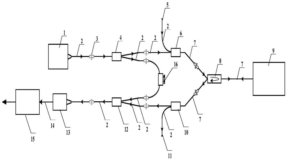
[0038] Embodiment: Real-time high-precision time-delay sensing device based on fiber optic Doppler interference, such as figure 1 As shown, it includes a fiber-coupled laser chip 1, a fiber beam splitter 4, a fiber polarization beam combiner 6, a three-port fiber optic circulator 8, a target fiber delay line 9, a fiber polarization beam splitter 10, a fiber beam combiner 12, an optical fiber Coupling photodetector 13, delay signal real-time processing board 15, multiple uniaxial transmission polarization maintaining optical fibers 2, multiple biaxial transmission polarization maintaining optical fibers 7. The fiber-coupled laser chip 1, the fiber beam splitter 4, the fiber beam combiner 12, and the fiber-coupled photodetector 13 are sequentially connected through a single-axis transmission polarization-maintaining fiber 2 along the signal output direction, and the output end of the fiber-coupled photodetector 13 It is communicatively connected with the input end of the delay s...


PUM


Abstract

The invention discloses a real-time high-precision delay sensing device and method based on optical fiber Doppler interference, and relates to the technical field of terahertz time-domain spectral imaging. In the prior art, the existing optical fiber Doppler displacement interferometer needs later data processing to realize sensing, real-time on-line measurement cannot be provided, and the delay line cannot be used at the same time when the delay line works. A purpose of the invention is to solve the problems in the prior art. According to the technical scheme, the device comprises an opticalfiber coupling laser chip, an optical fiber beam splitter, an optical fiber polarization beam combiner, a three-port optical fiber circulator, a target optical fiber delay line, an optical fiber polarization beam splitter, an optical fiber beam combiner, an optical fiber coupling photoelectric detector, a delay signal real-time processing board card, a plurality of single-axis transmission polarization maintaining optical fibers and a plurality of double-axis transmission polarization maintaining optical fibers. According to the invention, direct online measurement of the delay amount of a rotary optical delay line can be realized while the delay positioning precision of the rotary optical delay line is improved, so that a technical support is provided for high-precision terahertz time domain signal high-speed sampling of the high-speed optical fiber delay line and delay precision calibration of a common optical fiber delay line.

Description

technical field [0001] The invention relates to the technical field of terahertz time-domain spectral imaging, more specifically, it relates to a real-time high-precision time-delay sensing device and method based on fiber optic Doppler interference, and is especially suitable for high-precision terahertz imaging based on high-speed fiber delay lines. It is applicable to the field of high-speed sampling of time-domain signals, and it is also applicable to the field of delay accuracy calibration of ordinary optical fiber delay lines. Background technique [0002] The optical delay line is the core device of terahertz time-domain spectroscopy technology, which realizes the scanning detection of terahertz time-domain signals by changing the relative time delay between femtosecond probe light and terahertz pulse. Among various types of delay line technology, rotating optical delay line is the most common method to achieve large time-domain scanning range and high scanning repeti...

Claims


Application Information

Patent Timeline
IPC IPC(8): G01J3/42G01N21/3586G01J3/02G02B6/28G02B6/42G02B27/28
CPCG01J3/42G01N21/3586G01J3/0297G02B27/283G02B6/4286G02B6/2861G01J2003/423Y02A90/10
Inventor 刘乔冉茂杰王旭何徽高鹏钟森城朱礼国李泽仁
Owner INST OF FLUID PHYSICS CHINA ACAD OF ENG PHYSICS
Features
  • Generate Ideas
  • Intellectual Property
  • Life Sciences
  • Materials
  • Tech Scout
  • Unparalleled Data Quality
  • Higher Quality Content
  • 60% Fewer Hallucinations
Learn More