Nano-foam lifting liquid-draining gas production rod and preparation method and application

A liquid drainage gas recovery and foam lifting technology, which is applied in chemical instruments and methods, mining fluids, earth drilling and production, etc., can solve the problems of limited application range, low efficiency, water flooding and shutdown of gas wells, etc. , to achieve excellent resistance to condensate oil and methanol, enhance ultimate recovery, and restore gas well productivity

Inactive Publication Date: 2020-10-13
成都立联科能源科技有限公司
View PDF12 Cites 3 Cited by
  • Summary
  • Abstract
  • Description
  • Claims
  • Application Information

AI Technical Summary

Problems solved by technology

However, at present, more and more gas wells have serious liquid accumulation, and the gas flow velocity is extremely low, and even a large number of gas wells are flooded and shut down, and the gas flow velocity is zero, which cannot meet the conditions of agitation and foaming
This has resulted in low efficiency in the use of existing foam drainage agents, and

Method used


Image

  • Nano-foam lifting liquid-draining gas production rod and preparation method and application

Examples


Embodiment 1

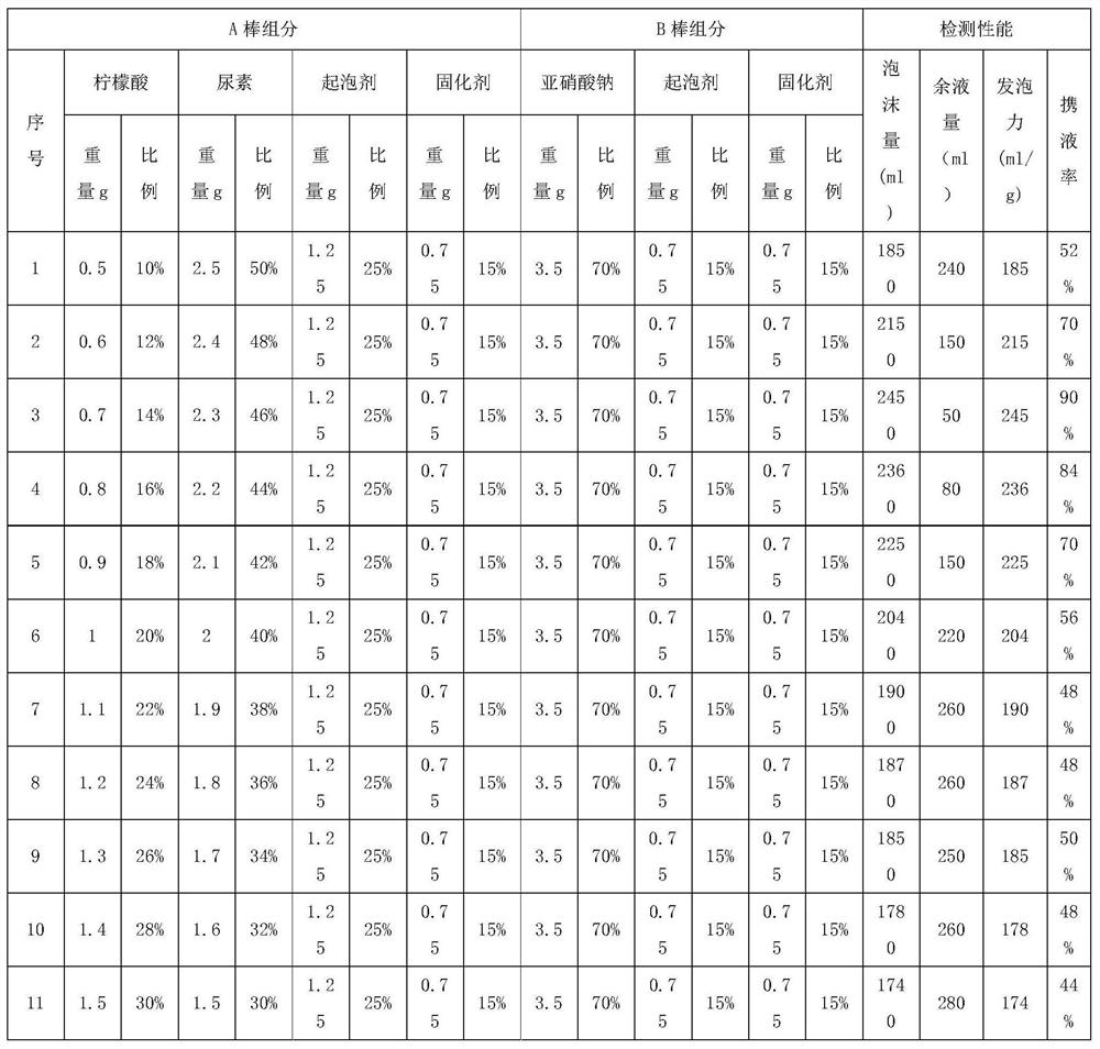
[0030] This embodiment provides a nano-foam lifting liquid drainage gas sampling rod, including a gas well foam lifting liquid drainage gas sampling rod A rod and a gas well foam lifting liquid drainage gas sampling rod B rod. Air stick A stick includes raw material components with the following mass ratio: 25-35 parts of surfactant sodium lauryl sulfate, 0.1-0.3 parts of foam stabilizer sodium perfluorononenyloxybenzenesulfonate, 15-25 parts Parts of curing agent OP-25, 10-15 parts of citric acid and 25-50 parts of urea; specifically, the surfactant sodium lauryl sulfate can be but not limited to 25 parts, 30 parts or 35 parts etc. etc., the specific amount is not limited, and it can be kept within the scope required by this embodiment according to the actual situation; the foam stabilizer sodium perfluorononenyloxybenzene sulfonate can be but not limited to 0.1, 0.2 part or 0.3 part, etc., the specific amount is not limited, and it can be kept within the scope required by th...

Embodiment 2

[0037] This embodiment is a further improvement made on the basis of Embodiment 1. The specific differences between this embodiment and Embodiment 1 are:

[0038] In this embodiment, it is further preferred that the gas well foam lifting liquid drainage gas extraction rod A rod specifically includes the following raw material components in mass proportion: 30 parts of surfactant sodium lauryl sulfate, 0.2 part of foam stabilizing agent Agent perfluorononenyloxybenzene sulfonate sodium, 20 parts of curing agent OP-25, 12 parts of citric acid and 37 parts of urea.

Embodiment 3

[0040] This embodiment is a further improvement made on the basis of Embodiment 1. The specific differences between this embodiment and Embodiment 1 are:

[0041] In this embodiment, it is further preferred that the gas well foam lifting liquid drainage gas extraction rod A rod specifically includes the following raw material components in mass proportion: 35 parts of surfactant sodium lauryl sulfate, 0.3 part of foam stabilizing agent Agent perfluorononenyloxybenzene sulfonate sodium, 25 parts of curing agent OP-25, 15 parts of citric acid and 50 parts of urea.


PUM


Abstract

The invention belongs to the technical field of natural gas well drainage, and discloses a nano-foam lifting liquid-draining gas production rod and a preparation method and application. The nano-foamlifting liquid-draining gas production rod comprises a rod body A and a rod body B. The preparation method comprises the following steps: heating and stirring raw material components of the rod body A, pouring the mixed materials into a cylindrical plastic grinding tool, performing cooling and molding; and heating and stirring raw material components of the rod body B, pouring the mixed materialsinto the cylindrical plastic grinding tool, and performing cooling and forming. The application method comprises the following steps that the rod body A and the rod body B are put into a shaft, a large amount of high-water-content foam is generated through a chemical reaction, and therefore accumulated liquid in the shaft is lifted out of a wellhead, and the purpose of liquid draining and repeatedproduction is achieved. Tests show that the foaming force of the nano-foam lifting liquid-draining gas production rod can reach 245 mL/g to the maximum. By means of the rod, a large number of gas wells which do not have conventional foam drainage conditions, such as wells with serious liquid accumulation, wells which are shut down due to flooding, large-water-volume wells and low-pressure small-production wells, can be recovered, the productivity is maintained, and the final recovery efficiency of the gas wells and the final exploitation benefits of gas fields are improved.

Description

technical field [0001] The invention belongs to the technical field of natural gas well drainage, and in particular relates to a nano-foam lifting liquid drainage gas extraction rod, a preparation method and application thereof. Background technique [0002] In recent years, a large number of low-pressure, low-yield, low-abundance and low-permeability tight gas reservoirs in China have been put into development. After the gas wells in this type of gas reservoir are put into production, the pressure and production decline rapidly. It cannot meet the liquid-carrying requirements in the production process of gas wells, resulting in liquid accumulation at the bottom of some gas wells or in the wellbore, which seriously affects the continuous and stable production of gas wells. Drainage gas recovery has long occupied the main position in the production and operation of this type of gas reservoir. Among the numerous drainage gas recovery technologies, the foam drainage gas recov...

Claims


Application Information

Patent Timeline
IPC IPC(8): E21B43/22E21B43/00C09K8/584
CPCE21B43/16E21B43/122C09K8/584C09K2208/10
Inventor 赵伟李春辉贺杰李劲擎
Owner 成都立联科能源科技有限公司
Why Eureka
Try Eureka