Warm drainage cooling equipment and method

A technology of warm drainage and equipment, applied in the field of warm drainage and cooling, can solve the problems of warm drainage kinetic energy, high energy consumption of flash cooling, and low efficiency that few technologies have paid attention to, and achieve lower cooling costs, high efficiency, and energy consumption low effect

Active Publication Date: 2020-10-16
武汉润德工程技术有限公司
View PDF10 Cites 0 Cited by
  • Summary
  • Abstract
  • Description
  • Claims
  • Application Information

AI Technical Summary

Problems solved by technology

The typical cooling process of warm wastewater is to flow warm wastewater into a vacuum chamber below the saturation pressure to cool down and create water. The energy for flash evaporation comes from the reduction of its own sensible heat, and the temperature of the steam generated by flash evaporation is generally only 4°C higher than the ambient temperature. It can only rely on the condensation of cooling water, and consumes a large amount of cooling water under the low temperature difference, which makes the energy consumption of flash cooling huge.
High energy consumption and low efficiency are regarded as the main obstacles to the large-scale promotion and application of existing cooling technologies. How to further reduce the energy consumption of warm water drainage and develop new low-cost cooling technologies are key issues that urgently need to be solved.
[0003] The thermal drainage of the power station is discharged to the sea through the thermal drainage ditches. The existing technologies tend to recycle the heat in the thermal drainage ditches, such as seafood farming, heat pump heating and heating in winter, etc., which are typical flash evaporation. The cooling process only recovers and utilizes the heat of warm drainage, and few technologies pay attention to the kinetic energy contained in warm drainage. The gravity head of warm drainage discharged from the condenser of the power station is about 6-10m, and the drainage flow rate is about 1-10m. 3m / s

Method used


Image

  • Warm drainage cooling equipment and method

Examples


Embodiment Construction

[0039] The present invention will be described in further detail below in conjunction with the accompanying drawings and embodiments.

[0040] At present, the most fundamental reason for the pollution of heat, drainage and heat is that energy has not been used most effectively and rationally. Coastal power stations are close to the sea. If the huge amount of waste heat resources and seawater resources along the power stations can be utilized according to local conditions, and the seawater desalination project can be combined with waste heat from warm water drainage, it will completely change the current situation of water pollution control.

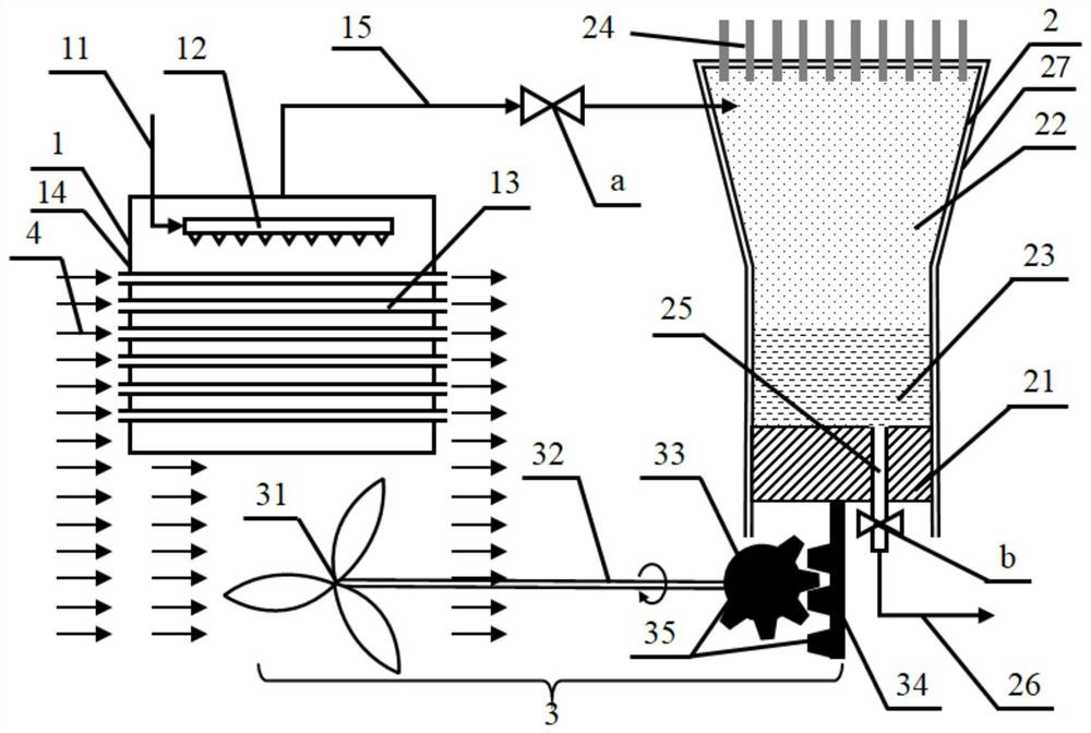
[0041] Therefore, the present invention proposes a warm drainage cooling device and method, referring to figure 1 As shown, the warm wastewater cooling equipment includes a cooling box 14, a compression condensing device 2, and a steam pipeline 15 connecting the cooling box 14 and the compression condensing device 2. The steam pipeline 15...


PUM


Abstract

The invention discloses warm drainage cooling equipment and a method, and belongs to the technical field of warm drainage cooling. The equipment comprises a cooling box which comprises a heat exchangetube bundle arranged in a penetrating manner, a spraying device arranged in the cooling box, and a seawater pipeline; a compressing and condensing device which comprises a condenser arranged at the top, a piston arranged at a bottom opening, a fresh water pipeline and a second valve arranged on the fresh water pipeline; a steam pipeline which is used for communicating the cooling box with the interior of the compressing and condensing device; and a first valve which is arranged on the steam pipeline. The equipment has the beneficial effects that the heat of warm discharged water of a power station can be absorbed through seawater evaporation, so that the warm discharged water of the power station is cooled, the thermal pollution influence of the warm discharged water on a sea area is relieved, seawater desalination is realized while the warm discharged water is cooled, and the economic cost of the power station warm discharged water cooling process is integrally reduced.

Description

technical field [0001] The invention relates to the technical field of warm drain cooling, in particular to a warm drain cooling device and method. Background technique [0002] The cooling water flow rate of millions of nuclear power units in operation in China is about 50-65m 3 / s, the drainage temperature rises to 6-11°C, warm drainage changes the ambient temperature of the water area, and changes the dominant species of organisms, especially benthic organisms; on the other hand, thermal shock will lead to sudden death of temperature-sensitive organisms. The typical cooling process of warm wastewater is to flow warm wastewater into a vacuum chamber below the saturation pressure to cool down and create water. The energy for flash evaporation comes from the reduction of its own sensible heat, and the temperature of the steam generated by flash evaporation is generally only 4°C higher than the ambient temperature. As a result, it can only rely on the cooling water to conden...

Claims


Application Information

Patent Timeline
IPC IPC(8): C02F1/04F28D3/02F28F27/00C02F103/08
CPCC02F1/04C02F1/043F28D3/02F28F27/00C02F2103/08C02F2303/10Y02A20/124
Inventor 胡雪蛟章先涛
Owner 武汉润德工程技术有限公司
Why Eureka
Try Eureka