Full-automatic feeding device of hard and brittle single crystal micro-cylinder outer circle ultrasonic auxiliary grinding machine
An ultrasonic-assisted and fully automatic technology, which is applied to the parts of grinding machine tools, grinding machines, and machine tools designed for grinding the rotating surface of workpieces, etc., can solve the difficulties of accurate positioning and clamping, broken workpieces, and low automation efficiency, etc. question
- Summary
- Abstract
- Description
- Claims
- Application Information
AI Technical Summary
Problems solved by technology
Method used
Image
Examples
specific Embodiment approach 1
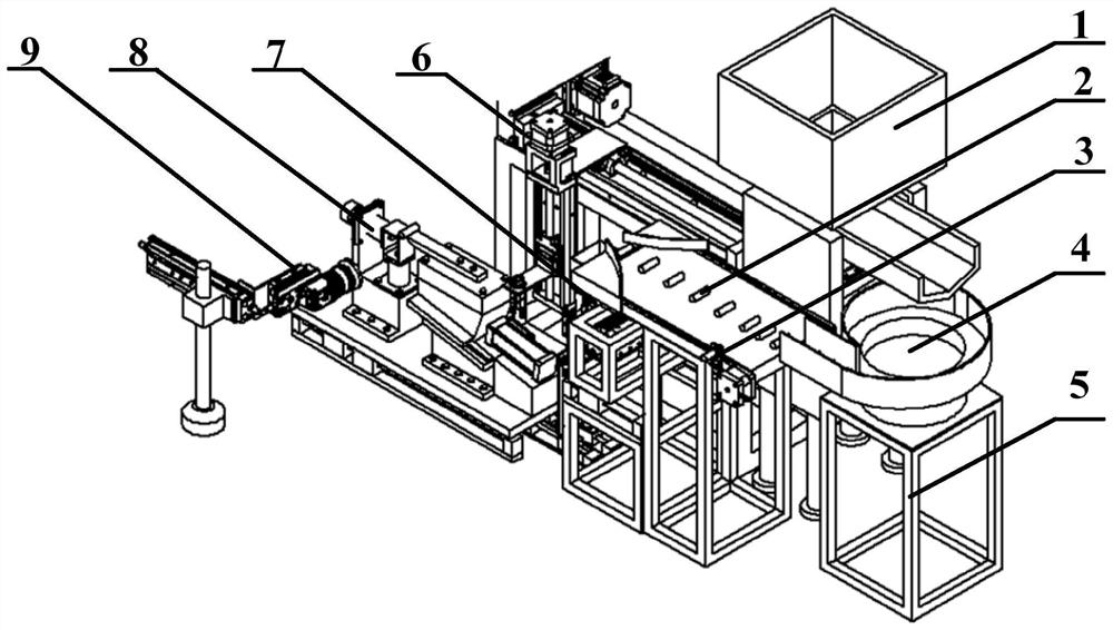
[0019] Specific implementation mode one: combine figure 1 Describe this embodiment, the fully automatic feeding device of the hard and brittle single crystal micro-cylindrical outer circle ultrasonic assisted grinder of this embodiment, it comprises hopper device 1, first photoelectric sensor 3, vibrating material plate 4, vibrating material plate support 5, Feeding mechanism 6, workpiece separation mechanism 7, ultrasonic elliptical vibration auxiliary grinding device 8 and online calibration camera device 9, the hopper device 1 is set above the vibrating material tray 4, and the discharge port 11 of the hopper device 1 is facing the vibrating material tray 4. The vibrating material tray 4 is installed on the vibrating material tray support 5, the outlet of the vibrating material tray 4 is connected to the workpiece separation mechanism 7, and the unprocessed workpiece 2 is discharged from the hopper device 1 and then automatically sorted after being output by the vibrating ma...
specific Embodiment approach 2
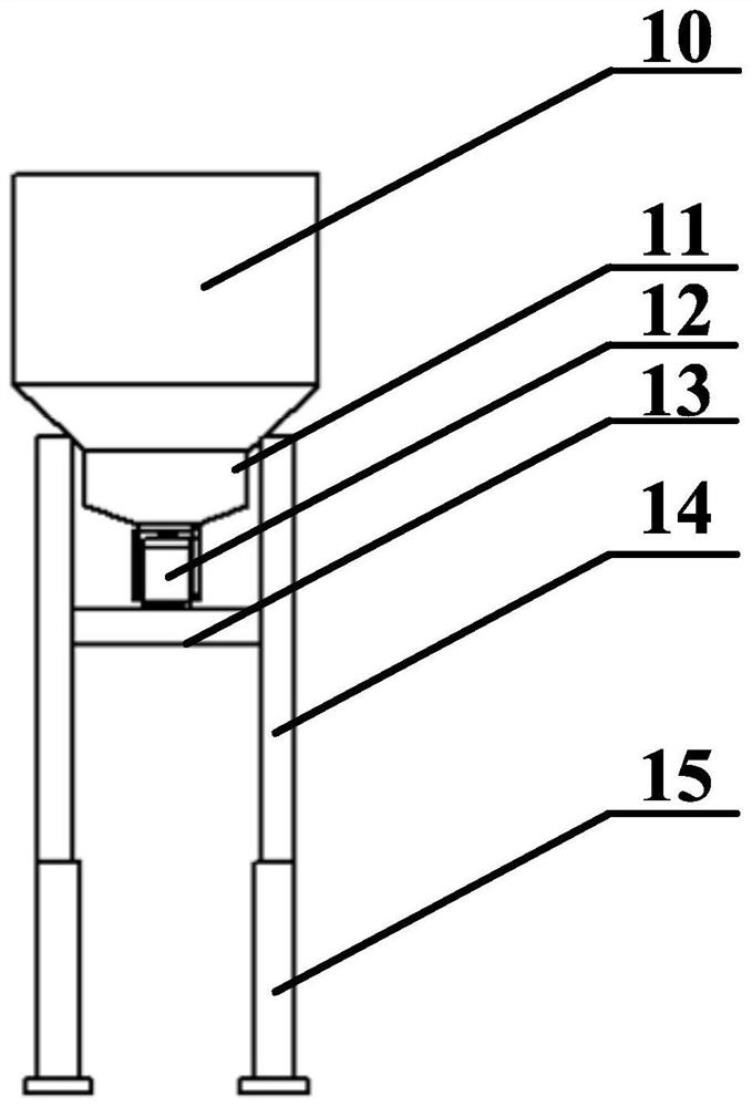
[0021] Specific implementation mode two: combination figure 1 and figure 2 Description of this embodiment, the hopper device 1 of this embodiment includes a hopper 10, a discharge port 11, a linear vibrator 12, a cylinder plate 13, two support covers 14 and four hopper pillars 15, the hopper 10, the outlet The feed port 11, the linear vibrator 12, and the placement cylinder plate 13 are arranged in sequence from top to bottom in the vertical direction, and two support covers 14 are arranged on the left and right sides of the feed bin 10 in the vertical direction, and the feed bin 10 is fixed and installed On both sides of the support cover 14, a discharge port 11 is provided below the silo 10, the discharge port 11 is fixedly connected to the linear vibrator 12, and the two sides of the linear vibrator 12 are fixed on the cylinder plate 13 , the two ends of the cylinder plate 13 are respectively fixed on two support covers 14, each support cover 14 below is provided with two...
specific Embodiment approach 3
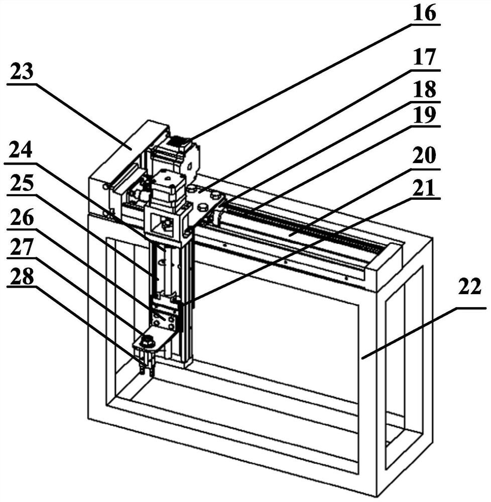
[0023] Specific implementation mode three: combination figure 1 and image 3Description of this embodiment, the feeding mechanism 6 of this embodiment includes a feed motor 16 in the X direction of the feeding mechanism, an L-shaped connector 17 in the X direction of the feeding mechanism, a linear motion mechanism 19 in the X direction of the feeding mechanism, and a fixed bracket for the feeding mechanism 22. X-direction feeding motor shield of the feeding mechanism 23. Z-direction linear motion mechanism of the feeding mechanism 25. Z-direction feeding motor of the feeding mechanism, Z-direction feeding motor shield of the feeding mechanism, Z-direction L of the feeding mechanism Type connecting piece 26, feeding mechanism clamp nut 27 and feeding mechanism air claw 28, feeding mechanism X direction linear motion mechanism 19 is horizontally arranged on the upper part of feeding mechanism fixed bracket 22, and feeding mechanism X direction linear motion Mechanism 19 compri...
PUM
 Abstract
Description
Claims
Application Information
 - R&D
- Intellectual Property
- Life Sciences
- Materials
- Tech Scout
- Unparalleled Data Quality
- Higher Quality Content
- 60% Fewer Hallucinations
Browse by: Latest US Patents, China's latest patents, Technical Efficacy Thesaurus, Application Domain, Technology Topic, Popular Technical Reports.
© 2025 PatSnap. All rights reserved.Legal|Privacy policy|Modern Slavery Act Transparency Statement|Sitemap|About US| Contact US: help@patsnap.com


