Neodymium-iron-boron magnet preparation device

A NdFeB system technology, applied in the direction of magnetic objects, inductors/transformers/magnets manufacturing, magnetic materials, etc., can solve the problems of inability to meet large-scale production, low production efficiency, and low product performance consistency

Pending Publication Date: 2020-10-23
山西通远科技有限公司
View PDF0 Cites 0 Cited by
  • Summary
  • Abstract
  • Description
  • Claims
  • Application Information

AI Technical Summary

Problems solved by technology

[0003] At present, the production efficiency of the existing NdFeB magnet preparation equipment on the market is low, and continuous production cannot be realized. The raw materials in the mold are unevenly laid, and the density of the produced NdFeB magnets is uneven. The product performance consistency is low, and it cannot meet large-scale production. needs

Method used


Image

  • Neodymium-iron-boron magnet preparation device
  • Neodymium-iron-boron magnet preparation device
  • Neodymium-iron-boron magnet preparation device

Examples


Embodiment 1

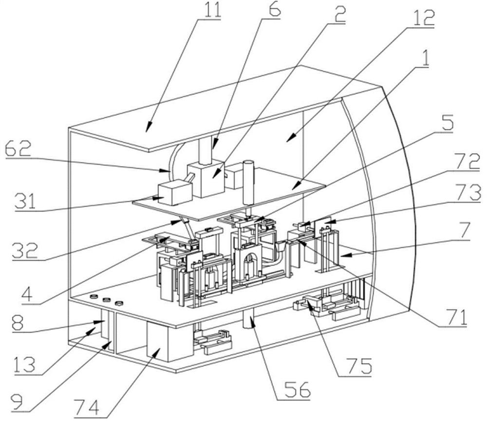
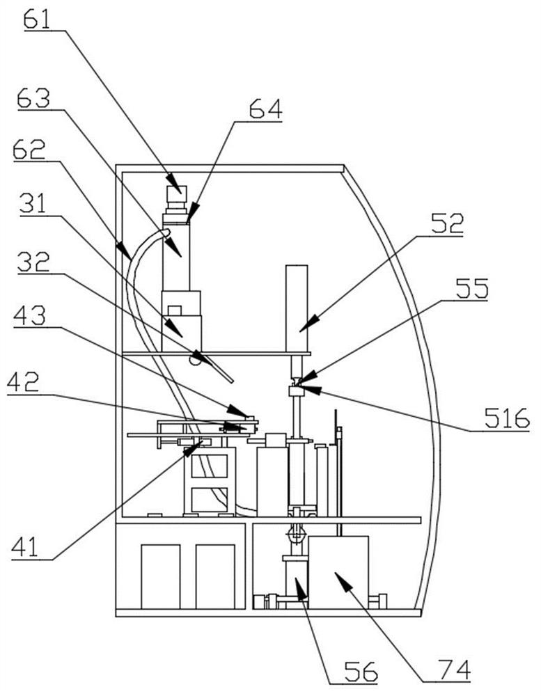
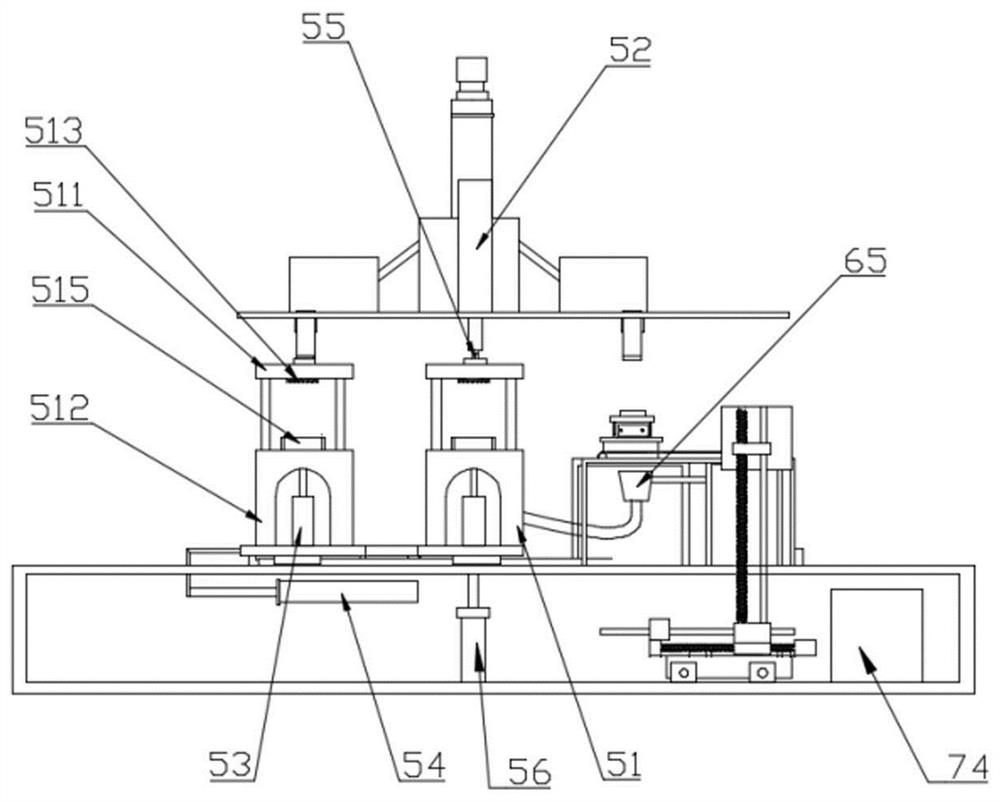
[0048] like Figure 1 to Figure 8 Shown: a NdFeB magnet preparation device, including a frame 1, a silo 2, a distributing device 3, a feeding device 4, a molding device 5, a coding device 6, a powder recovery device 7 and a control system;

[0049] The frame includes a working bin 12 and an auxiliary bin 13. The feed bin 2, the material distributing device 3, the feeding device 3, the molding device 5, the coding device 6, and the powder recovery device 7 are all arranged in the working bin. The control system includes electrical The cabinet 8 and the hydraulic system 9, the electrical cabinet and the hydraulic system are arranged in the auxiliary warehouse 13.

[0050] The silo 2 is set on the upper end of the frame 1, and the silo 2 is provided with an electromagnetic switch to control the powder output, and the electromagnetic switch is connected to the control system;

[0051] Said distributing device 3 comprises a weighing machine 31 and a distributing device 32, the wei...

Embodiment 2

[0073] like Figure 7As shown, the difference between this embodiment and Embodiment 1 is that the structure II in the dispenser also includes a cylinder III 355, and the cylinder III 355 is arranged below the cylinder I 352, and the axis of the cylinder III 355 and the axis of the cylinder I 352 Corresponding to the outer blanking point, the upper ends of the two flat plates II 353 coincide with the projection of the cylinder III 355 in the vertical direction, and the outer blanking of the cylinder I 352 is divided into two by the cylinder III 355 again; the distributor also includes a cylinder IV 356, the cylinder IV 356 is set under the cylinder III 355, the axis of the cylinder IV 356 corresponds to the inner blanking point of the cylinder III 355, and the cylinder IV 356 divides the inner blanking of the cylinder III into two again.

[0074] Operation method:

[0075] 1. The control system controls the electromagnetic switch of bin 2 to open, and bin 2 starts to discharg...


PUM


Abstract

The invention relates to a neodymium-iron-boron magnet preparation device which comprises a rack, a stock bin, material distribution devices, feeding devices, profiling devices, a stacking device, a powder recovery device and a control system. The stock bin is arranged at the upper end of the rack; the two material distribution devices are arranged on the left side and the right side of the rack respectively and comprise material weighing machines and material distributors correspondingly, wherein the material weighing machines are communicated with the stock bin, and the material distributorsare arranged at the lower ends of the material weighing machines; the number of the feeding devices is two, and the two feeding devices correspond to the two material distribution devices respectively; the number of die mechanisms is two; a transposition oil cylinder is arranged on the bottom side of the rack, and the transposition oil cylinder controls the die to conduct transposition operation;lower pressing blocks of the two die mechanisms are fixedly connected; and the distance between the two profiling devices meets the requirement that when any one profiling device is located at the profiling position, the other profiling device is located at the material filling position of one feeding device. The material distribution is uniform, the product consistency is high, and continuous production of products can be realized; and the invention relates to the technical field of neodymium-iron-boron magnet machining.

Description

technical field [0001] The invention relates to the technical field of NdFeB magnet processing, and more specifically relates to a NdFeB magnet preparation device. Background technique [0002] As one of the two major material pillars of today's information society, permanent magnet materials are becoming more and more important in the economic society. Permanent magnet materials are widely used in computer technology, information technology, aerospace, communication technology, transportation technology, office automation and other fields. [0003] At present, the production efficiency of the existing NdFeB magnet preparation equipment on the market is low, and continuous production cannot be realized. The raw materials in the mold are unevenly laid, and the density of the produced NdFeB magnets is uneven. The product performance consistency is low, and it cannot meet large-scale production. needs. Therefore, it is necessary to improve the prior art. Contents of the inv...

Claims


Application Information

Patent Timeline
Patent Type & Authority Applications(China)
IPC IPC(8): H01F41/02H01F1/057
CPCH01F1/0576H01F41/0266
Inventor 王向东
Owner 山西通远科技有限公司
Why Eureka
Try Eureka