Transmission mechanism of cyclone type milling machine

A technology of transmission mechanism and face milling machine, which is applied in the direction of milling machine equipment, milling machine equipment details, metal processing machinery parts, etc., which can solve the problem that the ratio between the speed of milling cutter and the speed of rotating body cannot be adjusted, the surface of the billet has obvious knife marks, and the tool is aggravated. Surface and other problems, to achieve the effect of facilitating processing implementation, broad market application prospects, and reducing milling vibration

Pending Publication Date: 2020-10-27
SUZHOU AOZHI INTELLIGENT EQUIP CO LTD
View PDF0 Cites 1 Cited by
  • Summary
  • Abstract
  • Description
  • Claims
  • Application Information

AI Technical Summary

Problems solved by technology

[0005] ①Although under normal circumstances, the down-milling effect of the milling cutter is better; but when the surface of the slab is uneven and has scale, the method of down-milling will lead to rough surface of the slab;
[0006] ②Because there will be a certain gap between the rotating body and each gear during the assembly process, then the method of down milling will cause vibration and cause the tool to increase the loss of the tool surface when it crawls on the surface of the slab;
[0007] ③Under the constraints of the existing structure, the ratio of the rotational speed of the milling cutter to the rotational speed of the rotating body cannot be adjusted, which will lead to obvious tool marks on the surface of the slab and affect the apparent quality

Method used


Image

  • Transmission mechanism of cyclone type milling machine
  • Transmission mechanism of cyclone type milling machine
  • Transmission mechanism of cyclone type milling machine

Examples


Embodiment 1

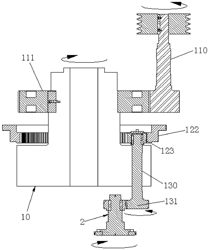
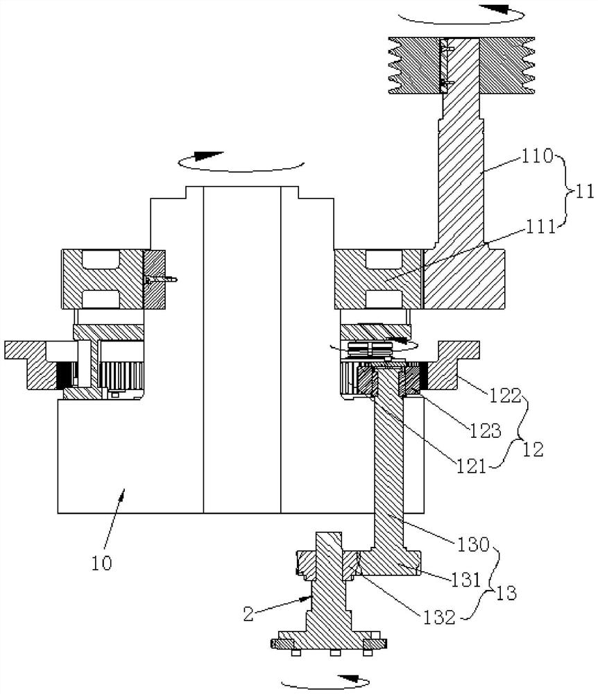
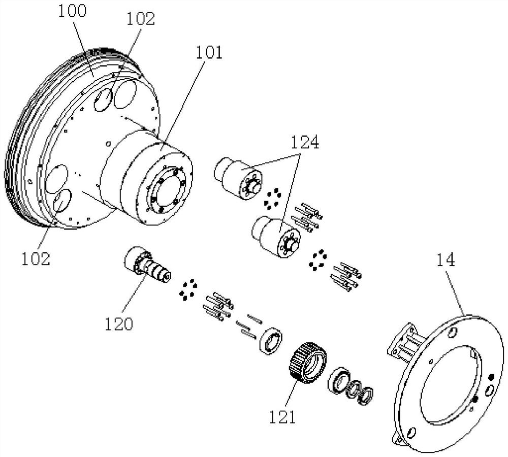
[0028] Please refer to the attached figure 2 And attached image 3 As shown in FIG. 1 and 2 , they are respectively a schematic sectional view and a partial exploded structural view of the transmission mechanism of the whirlwind noodle milling machine of the present invention.

[0029] The transmission mechanism of the cyclone type face milling machine in the present invention includes a rotating body 10, an input transmission assembly 11, an intermediate transmission assembly 12 and an output transmission assembly 13, wherein the rotating body 10 has a base 100 and is integrally formed on the base 100. The connecting shaft portion 101 on the side (the so-called "positive side" and "back side" are only for convenience of description, and are not used to limit the scope of the present invention). The input power transmission assembly 11 has a power supply to the motor The input shaft 110, which is positioned and connected to the output shaft, and a transmission gear A111 whic...


PUM


Abstract

The invention discloses a transmission mechanism of a cyclone type milling machine. The transmission mechanism comprises a rotating body, a force input transmission assembly, a middle transmission assembly and a force output transmission assembly. The rotating body is provided with a base part and a connecting shaft part, and the force input transmission assembly is provided with a force input shaft connected with a motor power output shaft and a transmission gear A sleeving the connecting shaft part and meshing with one shaft end of the force input shaft. The middle transmission assembly is provided with a transition shaft mounted on the base part, a transition gear disposed on the positive side of the base part and rotatably mounted on the transition shaft, a fixed gear ring sleeving theconnecting shaft part at an interval and meshing with the transition gear, and a transmission gear C connected to the base part and meshing with the fixed gear ring. The force output transmission assembly is provided with a force output shaft connected with the transmission gear C and a transmission gear B in transmission connection with a milling cutter, and the transmission gear B also sleevesone shaft end of the force output shaft. Application of the transmission mechanism of the cyclone type milling machine is close to actual working conditions, the integrity, smoothness and machining quality of the surface of a casting blank can be effectively guaranteed, and the cutter loss is effectively reduced.

Description

technical field [0001] The invention relates to the technical field of noodle milling equipment, and specifically provides a transmission mechanism of a whirlwind noodle milling machine. Background technique [0002] In the copper pipe processing industry, the first processing procedure for the hollow tube billet cast from the casting furnace is to remove the oxide layer on the outer surface, and this process is usually completed by the milling unit. [0003] attached figure 1 A schematic cross-sectional view of a transmission mechanism of a milling machine commonly used for milling an oxide layer on the surface of a hollow tube blank is shown. The working principle of the transmission mechanism of the noodle milling machine is as follows: firstly, the motor outputs power and drives the input shaft 110 to rotate, and then drives the rotating body 10 to rotate after transmitting the power through the transmission gear A111, and the After the power output by the rotating bod...

Claims


Application Information

Patent Timeline
Patent Type & Authority Applications(China)
IPC IPC(8): B23C3/00B23C9/00B23Q3/06B23Q11/00
CPCB23C3/00B23C9/00B23Q3/06B23Q11/0032
Inventor 肖建良包建平邝俊
Owner SUZHOU AOZHI INTELLIGENT EQUIP CO LTD
Why Eureka
Try Eureka