Aftertreatment device for motor vehicle exhaust and use method

A technology for exhaust gas post-processing and motor vehicles, which is applied in exhaust devices, noise reduction devices, machines/engines, etc., and can solve problems such as increased pollution gas, blockage of exhaust pipes, and health hazards, and achieves enhanced catalytic effects and increased The contact area and the effect of enhancing the heat dissipation effect

Inactive Publication Date: 2020-10-27
浙江机电职业技术学院
View PDF0 Cites 2 Cited by
  • Summary
  • Abstract
  • Description
  • Claims
  • Application Information

AI Technical Summary

Problems solved by technology

[0002] At present, with the progress of the times, automobiles have become an indispensable part of people's lives. However, although the development of the automobile industry has brought great benefits to mankind, it also pollutes our living environment. The exhaust gas produced by automobiles during driving contains Harmful gases, thus causing greater pollution to the atmosphere, especially in large and medium-sized cities, the number of automobiles is on the rise in a straight line, and the emission of automobile exhaust has caused great harm to the health of urban residents. It is the main cause of air pollution in modern cities. The main source, in order to solve the above problems, various automobile exhaust treatment devices have been developed. The existing exhaust gas treatment devices are three-way catalytic converters, but the use of three-way catalytic converters will have the following problems. Most of the first and three-way catalytic converters The interior is a catalyst carrie

Method used


Image

  • Aftertreatment device for motor vehicle exhaust and use method
  • Aftertreatment device for motor vehicle exhaust and use method
  • Aftertreatment device for motor vehicle exhaust and use method

Examples


Embodiment Construction

[0028] The present invention will be further described below in conjunction with accompanying drawing:

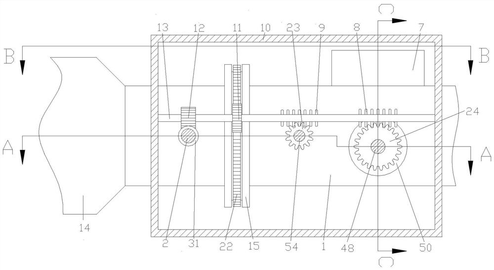
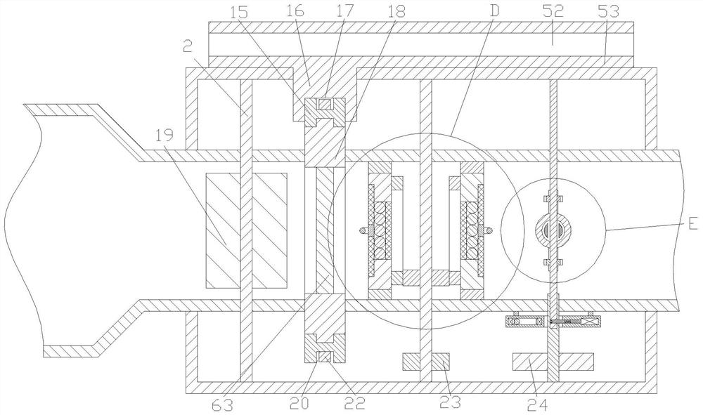
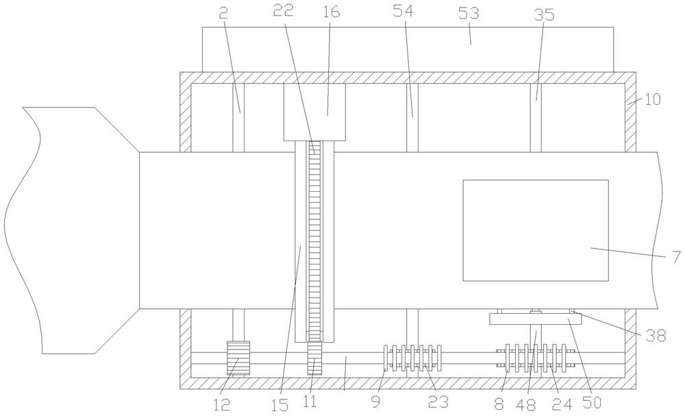
[0029] Refer to attached Figure 1-11 : In the present embodiment, this motor vehicle exhaust aftertreatment device comprises a first square pipe 1, a second square pipe 10 is fixedly installed on the outside of the first square pipe 1, and a first square pipe 1 is installed at one end of the first square pipe 1. Round pipe 14, the inside of the first square pipe 1 is symmetrically provided with a circular plate 61, and the outer side of the circular plate 61 is rotatably connected with a first support plate 56 fixedly connected to the inner wall of the first square pipe 1, and between the circular plates 61 After passing through the first square tube 1, the first rotating shaft 54 ​​that is rotatably connected to the inner walls of the front and rear ends of the second square tube 10, the center of the circular plate 61 is provided with a through first installation groove ...


PUM


Abstract

The invention discloses an aftertreatment device for motor vehicle exhaust. The aftertreatment device comprises a first square pipe; a second square pipe is fixedly mounted on the outer side of the first square pipe; a first round pipe is mounted at one end of the first square pipe; round plates are symmetrically arranged inside the first square pipe; and first supporting plates fixedly connectedwith the inner wall of the first square pipe are rotationally connected on the outer sides of the round plates. The aftertreatment device has the beneficial effects as follows: the aftertreatment device is simple in structure and convenient to operate, the condition that chippings produced by breakage of the aftertreatment device for the motor vehicle exhaust after collisions enter an exhaust pipeto block the exhaust pipe can be avoided, the contact time of the exhaust and a catalyst can be prolonged, the contact area of the exhaust and the catalyst can be increased, the temperature of the exhaust can be reduced, the exhaust can reach the optimal catalytic temperature, mist of the liquid catalyst can be mixed in the exhaust when the exhaust is about to be discharged out of the exhaust pipe, thus the exhaust is further degraded, and the practicability is high.

Description

technical field [0001] The invention relates to the technical field of tail gas treatment, in particular to a motor vehicle tail gas post-treatment device and a usage method. Background technique [0002] At present, with the progress of the times, automobiles have become an indispensable part of people's lives. However, although the development of the automobile industry has brought great benefits to mankind, it also pollutes our living environment. The exhaust gas produced by automobiles during driving contains Harmful gases, thus causing greater pollution to the atmosphere, especially in large and medium-sized cities, the number of automobiles is on the rise in a straight line, and the emission of automobile exhaust has caused great harm to the health of urban residents. It is the main cause of air pollution in modern cities. The main source, in order to solve the above problems, various automobile exhaust treatment devices have been developed. The existing exhaust gas tr...

Claims


Application Information

Patent Timeline
IPC IPC(8): F01N3/28F01N3/02F01N13/08F01N13/00
CPCF01N3/02F01N3/28F01N3/2803F01N13/00F01N13/082Y02A50/20
Inventor 顾盛挺祝勇仁
Owner 浙江机电职业技术学院
Why Eureka
Try Eureka