Hierarchical Quantification Method Based on Damage Mapped Finite Element Mesh

A quantitative method and finite element technology, applied in image analysis, design optimization/simulation, instruments, etc., can solve problems such as inability to reflect layered area distribution layered gradients, etc., achieve convenient remaining mechanical properties, high degree of automation, and improve simulation The effect of precision

Active Publication Date: 2022-05-10
SHANGHAI JIAOTONG UNIV
View PDF1 Cites 0 Cited by
  • Summary
  • Abstract
  • Description
  • Claims
  • Application Information

AI Technical Summary

Problems solved by technology

However, most of the existing equivalent delamination radii can only reflect the overall degree of delamination in the application process, and cannot reflect the regional distribution and delamination gradient of the delamination.

Method used


Image

  • Hierarchical Quantification Method Based on Damage Mapped Finite Element Mesh
  • Hierarchical Quantification Method Based on Damage Mapped Finite Element Mesh
  • Hierarchical Quantification Method Based on Damage Mapped Finite Element Mesh

Examples


Embodiment Construction

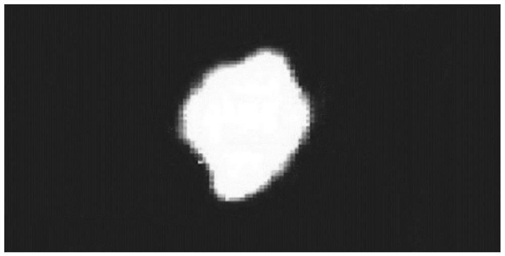
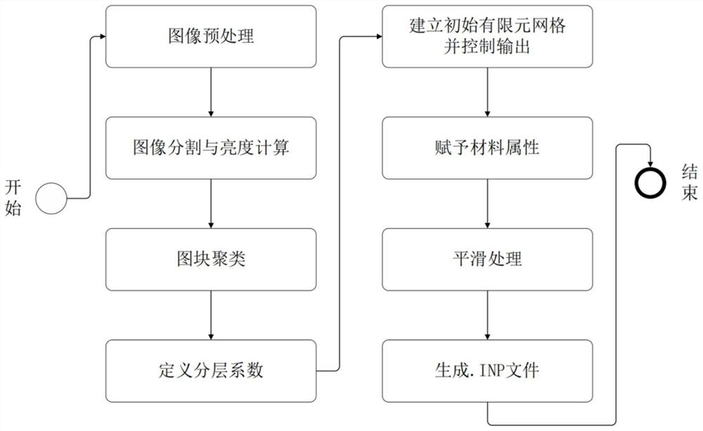
[0024] like figure 1 As shown, this embodiment relates to a method for quantifying drilling layers based on damage mapping finite element grids, including the following steps:

[0025] The first step: put a piece of figure 1 The image of the ultrasonic C-scan of the carbon fiber composite with holes shown and containing p×q pixels is imported into the MATLAB software, and its RGB value is read; then the RGB value is stored in a p×q×3 matrix; then Find the average value of the third dimension and convert it into an integer; finally store the average value in the p×q two-dimensional array D, and each element in D is the brightness of the pixel at the corresponding position.

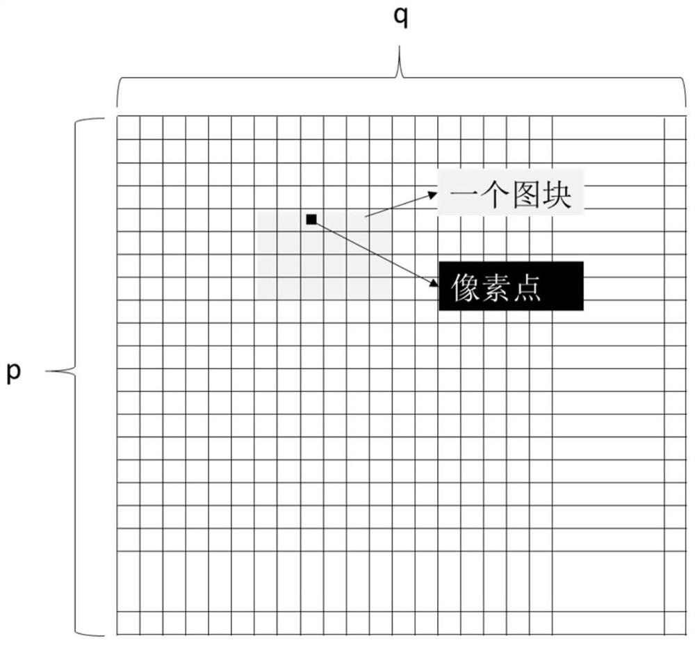
[0026] The second step: discretize the image into m×n blocks according to the precision of the finite element grid, each block defines the number i, i=1,2,...,m×n, such as image 3 shown. Calculate the average brightness of all pixels in each block, convert it into an integer, and store it in the m×n two...


PUM


Abstract

A layered quantification method based on the damage mapping finite element grid. The brightness value of the image obtained after ultrasonic scanning of the layered area of ​​the borehole is counted by blocks, and an initial finite element grid that is completely consistent with the topology of the block is established. And replace the material properties, and then smooth the finite element grid to get the optimized finite element model and export it as a text file of .INP. The present invention acquires damage information from ultrasonic C-scan images, can reflect the degree of damage on each unit, quantify the degree of stratification in different regions, and improve simulation accuracy; the overall degree of automation is high, and the direct connection from ultrasonic scan images to finite element calculation models can be realized. Generate, avoiding the process of building a geometric model. Ultimately, the effect of quantifying borehole delamination damage is achieved.

Description

technical field [0001] The present invention relates to a technology in the field of material mechanics, in particular to a method for quantifying the drilling layers of composite materials based on damage mapping finite element grids. Background technique [0002] Carbon fiber reinforced composite material (CFRP) is an advanced composite material formed by co-thermal curing of carbon fiber and epoxy resin matrix. When mechanically connecting with other materials, it is necessary to drill bolt or rivet holes on CFRP. During the drilling process The resulting delamination affects the remaining strength of the structure. In order to quantify the delamination damage, it is first necessary to collect the delamination morphology with the help of external equipment, and then analyze the obtained image to quantify the delamination degree. During this process, the concepts of delamination factor and equivalent delamination radius were proposed and developed to facilitate subsequent...

Claims


Application Information

Patent Timeline
Patent Type & Authority Patents(China)
IPC IPC(8): G06F30/23G06T7/00G16C60/00G06F119/14
CPCG06F30/23G06T7/0002G16C60/00G06F2119/14
Inventor 朱平张磊刘钊
Owner SHANGHAI JIAOTONG UNIV
Why Eureka
Try Eureka