Garbage treatment device for new energy production and using method thereof

A garbage disposal device and new energy technology, applied in the direction of grain treatment, separation methods, chemical instruments and methods, etc., can solve the problems of waste of resources, increase of labor intensity, bad smell, etc., and achieve good crushing effect and structure The design is reasonable and the effect of improving the effect

Inactive Publication Date: 2020-11-03
安徽壹聘乐职科技有限公司
View PDF0 Cites 29 Cited by
  • Summary
  • Abstract
  • Description
  • Claims
  • Application Information

AI Technical Summary

Problems solved by technology

[0003] The existing garbage disposal device has a single function, and the crushing of garbage is not thorough enough, which increases the difficulty of subsequent garbage disposal and reduces the processing efficiency; in addition, due to the long-term treatment of garbage in the existing garbage disposal device, there are many garbage residues and residues in the device. Stolen goods, inconvenient to clean not only lead to dirty and smelly inside of the device, but also affect the operation of the device and garbage disposal, reducing the service life; at the same time, the existing garbage disposal device cannot use iron, iron, nickel, and cobalt in the garbage as the majority of the matrix Alloys are separated from other garbage, which leads to being mixed with the collected garbage and cannot be used, which not only increa...

Method used


Image

  • Garbage treatment device for new energy production and using method thereof
  • Garbage treatment device for new energy production and using method thereof
  • Garbage treatment device for new energy production and using method thereof

Examples


Embodiment 1

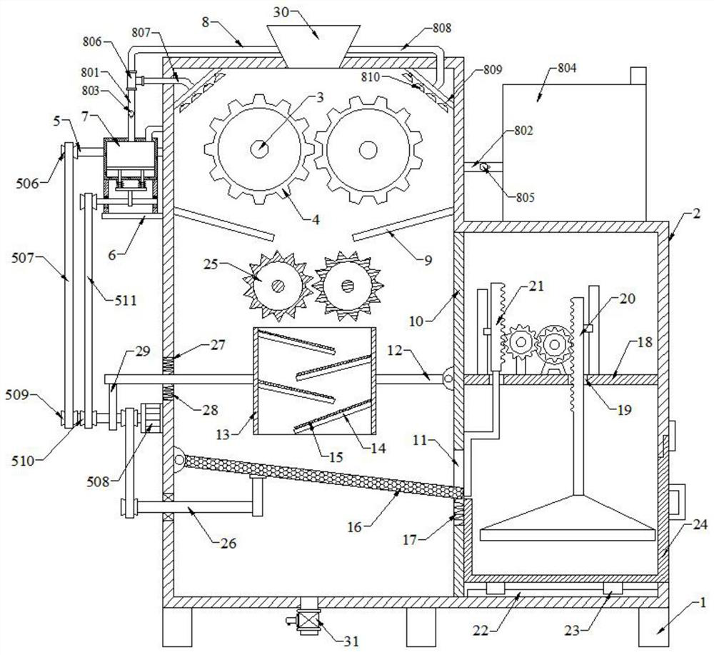
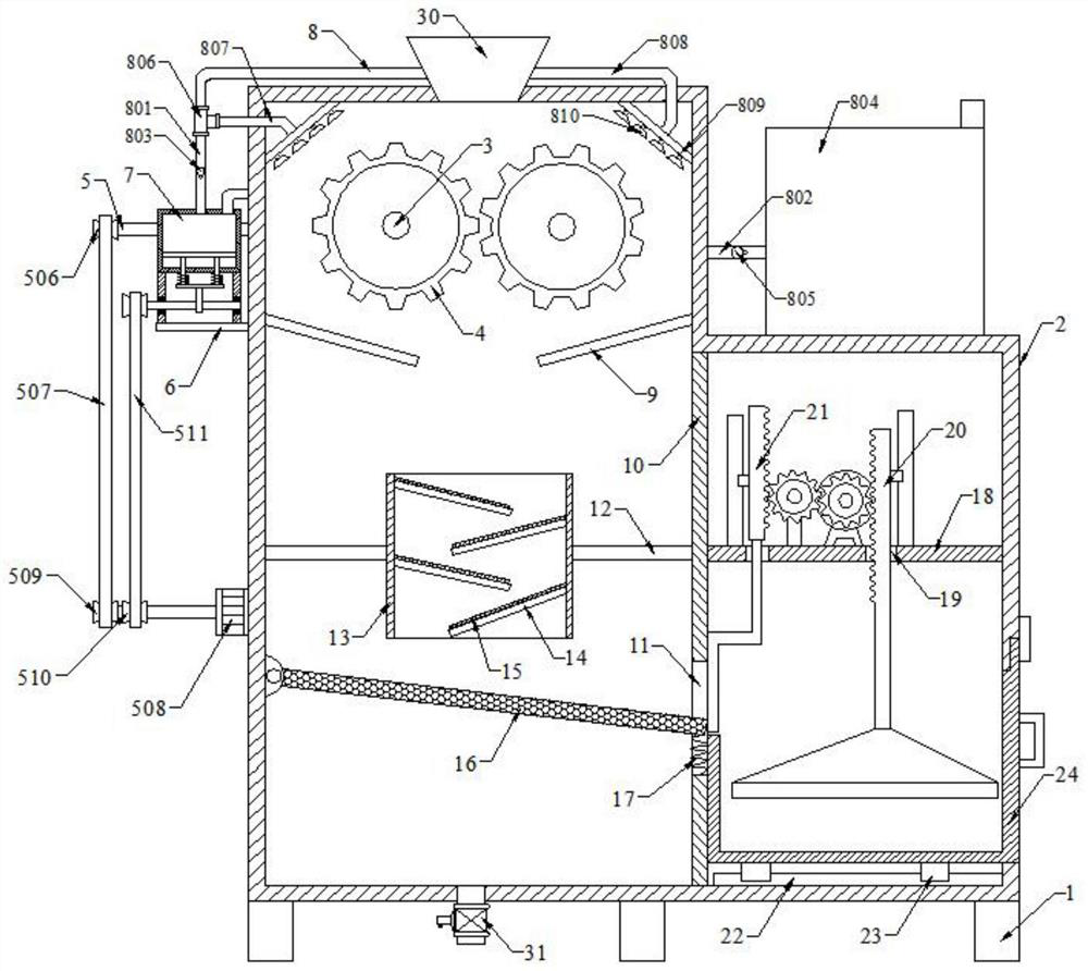
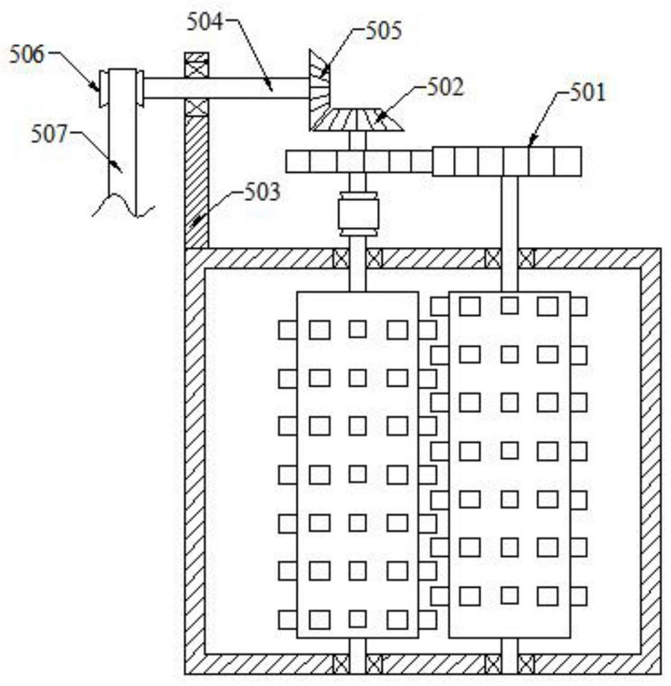
[0047] Please refer to the accompanying drawings, the present embodiment is a waste treatment device for new energy production, including a support 1, a treatment box 2 is arranged on the upper end of the support 1, and two first A rotating shaft 3, the crushing roller 4 is installed on the first rotating shaft 3, the transmission assembly 5 is connected to the rear end of the first rotating shaft 3, the support plate 6 is fixedly connected to the left wall of the processing box 2, and the water pressure assembly 7 is arranged on the upper end of the support plate 6 , the pressurized water assembly 7 is connected with a spray assembly 8, the left and right inner walls of the processing box 2 are symmetrically fixed with a material guide plate 9, the middle part of the processing box 2 is vertically provided with a partition 10, and the lower side of the partition 10 is provided with a feed chute 11, The left wall of the inner cavity of the processing box 2 and the left end of t...

Embodiment 2

[0066] Please refer to the accompanying drawings, on the basis of Embodiment 1, it also includes a crushing assembly 25, the crushing assembly 25 includes two third rotating shafts 2501, the third rotating shaft 2501 is rotatably connected to the front and rear side walls of the processing box 2, and the third rotating shaft 2501 The crushing roller 2502 is installed on the top, the rear end of the third rotating shaft 2501 on both sides is provided with the fourth spur gear 2503, the meshing transmission between the fourth spur gears 2503 on both sides, the third rotating shaft 2501 on the left side is provided with the fifth belt Pulley 2504, the third belt 2505 is installed on the fifth pulley 2504, the sixth pulley 2506 is arranged on the rear side of the first rotating shaft 3 on the left side, the sixth pulley 2506 is connected with the fifth pulley 2504 through the third belt 2505 .

[0067] Specifically, step S7 is also included: when the garbage crushed by the two cru...

Embodiment 3

[0069] Please refer to the accompanying drawings, on the basis of Embodiment 1, a vibration assembly 26 is also included, and the vibration assembly 26 includes a fourth rotating shaft 2601. The second cam 2602, the left end of the fourth rotating shaft 2601 is provided with the seventh pulley 2603, the fourth belt 2604 is installed on the seventh pulley 2603, the output end of the first servo motor 507 is provided with the eighth pulley 2605, the eighth pulley 2605 is in drive connection with the seventh pulley 2603 through the fourth belt 2604, and the left end of the filter plate 16 is hinged to the left wall of the inner chamber of the processing box 2.

[0070] Specifically, step S8 is also included: According to Embodiment 1, the first servo motor 507 rotates and drives the eighth pulley 2605 to rotate, and the eighth pulley 2605 drives the seventh pulley 2603 and the fourth rotating shaft 2601 through the fourth belt 2604 Rotate, thereby driving the second cam 2602 to r...


PUM


Abstract

The invention discloses a garbage treatment device for new energy production and a using method thereof. The garbage treatment device comprises a supporting seat, a treatment box is arranged at the upper end of the supporting seat, the rear end of a first rotating shaft is connected with a transmission assembly, a water-pressing assembly is arranged at the upper end of a supporting plate and communicates with a spraying assembly, a material-squeezing assembly is arranged on a transverse plate, and the left side of the material-squeezing assembly is connected with a material-blocking assembly.Crushing rollers on the two sides rotate oppositely to grind and crush garbage, the two crushing rollers and the garbage are cleaned through the water-squeezing assembly and the spraying assembly, through a material-passing cylinder, most of alloys in the garbage can be attracted by electromagnets, a filter plate realizes solid-liquid separation of garbage waste liquid, through downward moving ofa material-blocking plate, the garbage can be intermittently discharged, and the garbage is squeezed by the material-squeezing assembly so that more spaces can be saved for storing the more garbage, the treatment frequency is lowered, smashing rollers on the two sides rotate oppositely to further smash the garbage, thus the garbage is crushed more thoroughly, and the solid-liquid separation efficiency is improved through a vibrating assembly.

Description

technical field [0001] The invention relates to the technical field of shredding, impurity removal and compression of new energy production waste, in particular to a new energy production waste treatment device and a use method. Background technique [0002] New energy is also called unconventional energy. Refers to various forms of energy other than traditional energy. Refers to the energy that has just begun to be developed and utilized or is being actively researched and to be promoted. New energy generally refers to renewable energy that is developed and utilized on the basis of new technologies, including solar energy, biomass energy, wind energy, geothermal energy, wave energy, and ocean current energy. and tidal energy, as well as the thermal cycle between the ocean surface and the deep layer; in addition, there are hydrogen energy, biogas, alcohol, methanol, etc., and coal, oil, natural gas, water energy and other energy sources that have been widely used are called...

Claims


Application Information

Patent Timeline
IPC IPC(8): B09B3/00B02C4/08B02C4/40B02C23/20B01D29/03B03C1/02B30B9/30
CPCB09B3/00B02C4/08B02C4/40B02C23/20B01D29/03B03C1/02B30B9/3067B02C2201/06B09B3/20B09B2101/02
Inventor 王鹏
Owner 安徽壹聘乐职科技有限公司
Why Eureka
Try Eureka