Solid waste pyrolysis and related gas combustion device

A solid waste and combustion device technology, applied in the field of energy saving and environmental protection, can solve the problems of large consumption, secondary pollution, hindering pyrolysis, etc. Effect

Pending Publication Date: 2020-11-03
FOSHAN HUAJIEYUAN THERMAL ENERGY & ENVIRONMENTAL ENG TECH CO
View PDF0 Cites 2 Cited by
  • Summary
  • Abstract
  • Description
  • Claims
  • Application Information

AI Technical Summary

Problems solved by technology

[0002] High-temperature pyrolysis is one of the effective means of harmless reduction treatment of solid waste such as sludge and garbage. If these solid wastes are directly burned, a large amount of harmful tail gas will be generated to pollute the environment due to insufficient combustion, and it will cost a lot of money. The cost of exhaust gas purification, but also because the combustion of solid substances requires the use of excessive combustion air, resulting in the loss of a large amount of flue gas heat and energy consumption
However, the typical vertical pyrolysis furnace in the existing pyrolysis equipment has problems such as complex structure, high energy consumption and poor safety.
The water sealing method adopted by the vertical pyrolysis furnace to avoid the leakage of toxic gas from the slag outlet not only causes the heat of the slag to be cooled by water and wastes heat energy, but also produces a large amount of water vapor rising when the high-temperature slag meets water and is absorbed by the material again. Substances with heavy mud content are prone to bonding, resulting in poor air permeability and compaction, which hinders the normal progress of pyrolysis and increases energy consumption. This equipment needs to consume solid waste such as sludge with low calorific value A large amount of energy consumption for dehydration before pyrolysis has greatly increased the treatment cost and has not been widely used
[0003] Traditional pyrolysis devices need to produce high-concentration combustible gas before they can be used in combustion devices such as hot blast stoves. Since high-concentration combustible gas leaks, it will easily cause personnel poisoning and gas explosion risks, posing a great safety hazard
In addition, there are usually harmful gases in solid waste storage and operation areas, including the drying and dehumidification of solid waste before pyrolysis, which is also accompanied by the generation of harmful gases. The previous method is to deal with it through other waste gas treatment settings. Common methods include water spraying These methods have problems such as poor treatment effect, high treatment cost and secondary pollution.

Method used


Image

  • Solid waste pyrolysis and related gas combustion device
  • Solid waste pyrolysis and related gas combustion device
  • Solid waste pyrolysis and related gas combustion device

Examples


Embodiment 1

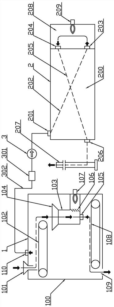
[0027] Embodiment 1: as figure 1 , a solid waste pyrolysis and related gas combustion device, including a solid processor 1, a gas burner 2 and a fan 3, the solid processor 1 includes a housing 100, a raw material conveying mechanism 102, a pyrolysis furnace 103, The slag conveying mechanism 108; the raw material conveying mechanism 102, the pyrolysis furnace 103, its inlet 104, the outlet 105, and the slag conveying mechanism 108 are all arranged in the housing 100; the housing 100 is provided with a raw material inlet 101 and a slag outlet 109 And the exhaust port 110; the raw material inlet 101 sends the raw material to the inlet of the pyrolysis furnace 103 through the raw material delivery mechanism 102, and the outlet of the pyrolysis furnace 103 delivers the raw material to the slag outlet 109 through the slag delivery mechanism 108; the described The air outlet 110 is located near the raw material inlet 101, and the air outlet 110 is located above the pyrolysis furnace...

Embodiment 2

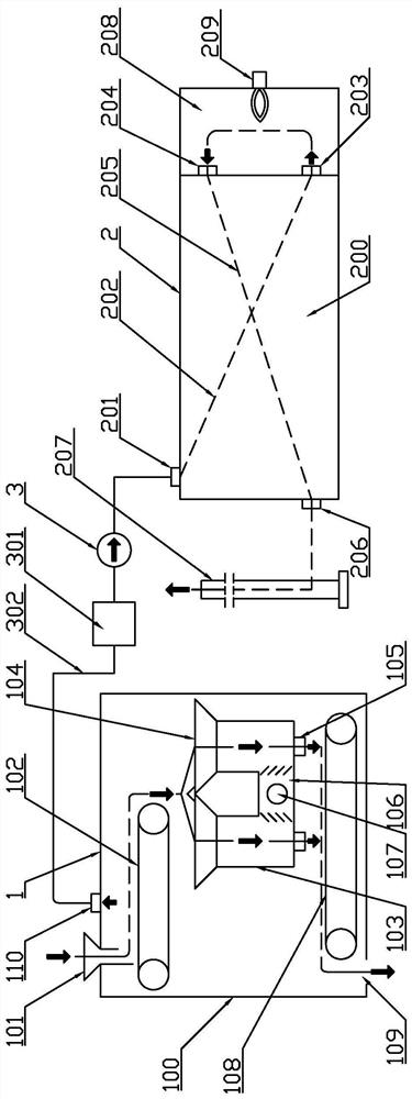
[0044] Embodiment 2: as figure 2 : A solid waste pyrolysis and related gas combustion device, including a solid processor 1, a gas burner 2 and a fan 3, the solid processor 1 includes a housing 100, a raw material delivery mechanism 102, a pyrolysis furnace 103, Slag conveying mechanism 108; described raw material conveying mechanism 102, pyrolysis furnace 103 and its inlet 104, outlet 105, and slag conveying mechanism 108 are all arranged in the housing 100; described housing 100 is provided with raw material inlet 101, outlet A slag port 109 and an exhaust port 110; the raw material inlet 101 sends the raw material to the inlet of the pyrolysis furnace 103 through the raw material delivery mechanism 102, and the outlet of the pyrolysis furnace 103 delivers the raw material to the slag outlet 109 through the slag delivery mechanism 108; The air exhaust port 110 is located near the raw material inlet 101; the air exhaust port 110 is located above the pyrolysis furnace inlet; ...

Embodiment 3

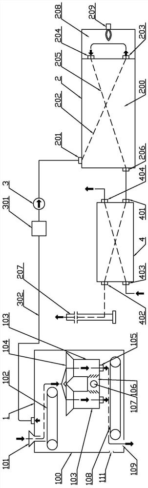
[0055] Embodiment 3: as image 3 : A solid waste pyrolysis and related gas combustion device, including a solid processor 1, a gas burner 2 and a fan 3, the solid processor 1 includes a housing 100, a raw material delivery mechanism 102, a pyrolysis furnace 103, Slag conveying mechanism 108; described raw material conveying mechanism 102, pyrolysis furnace 103 and its inlet 104, outlet 105, and slag conveying mechanism 108 are all arranged in the housing 100; described housing 100 is provided with raw material inlet 101, outlet Slag port 109, air exhaust port 110 and external waste gas suction port 111; described raw material inlet 101 sends raw material to the inlet of pyrolysis furnace 103 through raw material conveying mechanism 102, and its outlet of pyrolytic furnace 103 conveys raw material through slag conveying mechanism 108 to the slag outlet 109; the air exhaust port 110 is located near the position of the raw material inlet 101; the air exhaust port 110 is located a...


PUM


Abstract

The invention discloses a solid waste pyrolysis and related gas combustion device. The device comprises a solid processor, a gas combustor and a draught fan; the solid processor comprises a shell, a raw material conveying mechanism, a pyrolyzing furnace and a slag conveying mechanism; the gas combustor comprises a heat exchanger and a combustion chamber, wherein the heat exchanger is provided withan air inlet channel and an air outlet channel which are isolated from each other and can exchange heat with each other, wherein the air inlet channel is provided with a waste gas inlet and a waste gas outlet, and the air outlet channel is provided with a flue gas inlet and a flue gas outlet; and the waste gas outlet and the flue gas inlet communicate with the combustion chamber, the waste gas inlet communicates with an air extraction port through a pipeline and the draught fan, and the flue gas outlet communicates with a chimney. According to the device, the problem that combustible gas generated by pyrolysis is difficult to combust after being diluted due to the fact that a large amount of fresh air is sucked in due to air extraction conducted on the solid processor is solved; and the technological process is simplified, and the equipment investment can be reduced.

Description

technical field [0001] The invention relates to a device for solid waste pyrolysis and related gas combustion, in particular to a pyrolysis device applied to solid waste reduction and harmless treatment and coordinated with harmful gas treatment, which belongs to energy-saving and environmental protection technology field. Background technique [0002] High-temperature pyrolysis is one of the effective means of harmless reduction treatment of solid waste such as sludge and garbage. If these solid wastes are directly burned, a large amount of harmful tail gas will be generated to pollute the environment due to insufficient combustion, and it will cost a lot of money. The cost of exhaust gas purification is also high because the combustion of solid substances requires the use of excessive combustion air, which causes a large amount of flue gas heat loss and consumes energy. However, the typical vertical pyrolysis furnace in the existing pyrolysis equipment has problems such a...

Claims


Application Information

Patent Timeline
Patent Type & Authority Applications(China)
IPC IPC(8): F23G5/027F23G5/44F23G5/46
CPCF23G5/027F23G5/44F23G5/444F23G5/46
Inventor 林建东徐健元陈永基
Owner FOSHAN HUAJIEYUAN THERMAL ENERGY & ENVIRONMENTAL ENG TECH CO
Why Eureka
Try Eureka